


Getting Started Getting Started
4
ENGLISH
ENGLISH
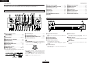
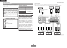
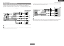
Display
q
Signal channel indicator
Lights when the preset channel is displayed at
w
.
w
Information display
e
Input signal indicators
r
Master volume indicator
This displays the volume level.
The Setup item number is displayed in System
Setup.
t
STEREO indicator
This lights when an FM stereo broadcast has
been received.
y
AUTO indicator
This lights when the broadcast station is
selected in the AUTO tuning mode.
u
TUNED indicator
This lights when an FM/AM broadcast has been
received.
i
RDS indicator
This lights when an RDS broadcast has been
received.
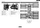
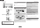
Part names and functions
Front panel
For details on the functions of these parts, refer to the pages given in parentheses ( ).
q
Power operation button
(ON/STANDBY)··········································(10)
w
Power indicator ·········································(10)
e
Power switch ·······································(10, 35)
r
Headphones jack (PHONES)·····················(19)
t
ANALOG button ········································(18)
y
SPEAKER buttons································(10, 35)
u
SURROUND BACK button ························(21)
i
SHIFT button··············································(30)
o
USER MODE buttons ································(33)
!0
PRESET buttons···································(29, 30)
!1
V. AUX INPUT terminals
Remove the cap covering the terminals when
you want to use them.
!2
SETUP MIC jack ·········································(10)
!3
SYSTEM SETUP button ····························(38)
!4
SURR. MODE/SURR. PARA button··········(18)
!5
SELECT/ENTER knob ··························(20, 28)
#0 @8 @6@9
@7
@3@5 @2 !9 !7@1
@0
!8@4
r y i o !1 !4!2 !5 !6
q
w
t
e
u !0
!3
rtiyu
w
e
q
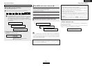
!6
Cursor buttons (
DD
,
HH
)·······························(21)
!7
MASTER VOLUME control knob··············(18)
!8
TUNING buttons (•, ª) ·····························(30)
!9
RT button····················································(32)
@0
PTY button ·················································(31)
@1
RDS button·················································(31)
@2
SURROUND BACK indicator·····················(21)
@3
Display
@4
INPUT mode indicators·····························(18)
@5
SIGNAL indicators·····································(21)
@6
BAND button··············································(30)
@7 EXT. IN button············································(18)
@8
Remote control sensor································(3)
@9
INPUT MODE button·································(18)
#0
INPUT SELECTOR knob ····························(18)
• The SELECT/ENTER knob on the main unit operates in
the same way as the CURSOR
FF
and
GG
buttons on
the remote control unit.
• The control functions in the same way as the
CURSOR
FF
button when turned counterclockwise,
as the CURSOR
GG
button when turned clockwise.
• The control functions in the same way as the
ENTER button when pressed the knob.