


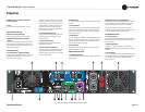
Operation Manual
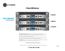
I-Tech HD Series Power Amplifi ers
page 8
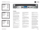
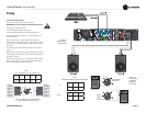
2.3.2 Choose Input Wire and Connectors
Crown recommends using pre-built or professionally wired,
bal anced line (two-conductor plus shield), 22-24 gauge cables
and connectors. Use 3-pin male XLR connectors.
Unbalanced line may also be used but may result in noise over
long cable runs.
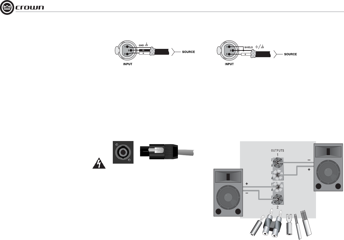
Figure 2.5 shows connector pin assignments for balanced analog
wiring or AES/EBU digital wiring. The use of standard analog
cable with AES/EBU will result in diminished performance. For
best results, 110 ohm shielded twisted-pair cable for AES/EBU
signals is highly recommended. Figure 2.6 shows connector pin
assignments for unbalanced analog wiring.
NOTE: Custom wiring should only be performed by qualifi ed
per sonnel.
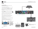
2.3.3 Choose Output Wire and Connectors
Crown recommends using pre-built or professionally wired, high-
quality, two- or four-conductor, heavy gauge speaker wire and
connectors. Use Class 2 output wiring. You may use a 4-pole
Speakon
®
connector (Figure 2.7) or banana plugs, spade lugs, or
bare wire for your output connectors (Figure 2.8). To prevent the
possibility of short circuits, wrap or otherwise insulate exposed
loudspeaker cable connectors.
CAUTION – SHOCK HAZARD: Potentially lethal voltages
exist at the output connectors when the amplifi er is
turned on and is passing a signal.
Using the guidelines below, select the appropriate size of wire
based on the distance from amplifi er to speaker.
Distance Wire Size
up to 25 ft. 16 AWG
26-40 ft. 14 AWG
41-60 ft. 12 AWG
61-100 ft. 10 AWG
101-150 ft. 8 AWG
151-250 ft. 6 AWG
CAUTION: Never use shielded cable for output wiring.
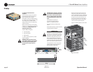
Figure 2.5
Balanced Analog Input Connector Wiring or
AES/EBU Digital Connector Wiring
Figure 2.6 Unbalanced Analog Input Connector Wiring
2 Setup
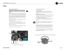
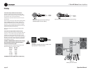
Figure 2.8
Binding Post Connections
Figure 2.7
Left: Speakon
®
Output Connector on Back Panel
Right: Speakon
®
Cable Connector