


Operation Manual
I-Tech HD Series Power Amplifi ers
page 34
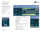
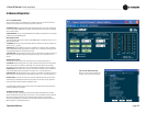
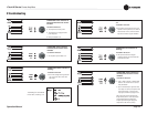
4.8.13 Amplifi er Settings
The Amplifi er Output Enable button turns each channel on
or off.
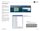
Error Reporting
The I-Tech amplifi er can detect four different error conditions
per channel and errors in the AC line voltage. Each error type
can be indi vidually confi gured to report the error through the
network. Network reported errors appear in the control software
Event Log. The following describes each error source.
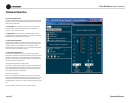
Clip: A clip detector is provided each channel. These monitors
will indicate any clip condition (> 0.05% distortion) in the
amplifi er channel. The clip detectors also can indicate Thermal
Level Control limiting.
The I-Tech HD can be confi gured to report if an excessive
number of output clip events occur in either amplifi er channel.
The clip events are consider an error if they exceed the defi ned
count per the defi ned unit of time.
The Count Control sets the maximum number of events before
the error is reported. The range is 1 to 100. The Time Control
defi nes the amount of time that the events are counted before
starting the counting process over. Its range is 1 to 10 seconds.
Note: Clip events are defi ned as the start of each clip and every
10 milliseconds the amplifi er is in clip thereafter. Using a high
count set ting with a short time setting may result in clip errors
never being detected.
Thermal: Errors can be generated for excessive temperature
in the output section of the amplifi er channel. The Threshold
Control sets the level that, if exceeded, will generate the error
report. This control has a range of 1 to 100%.
Line voltage: The AC line voltage can be monitored and an
error generated whenever the voltage is outside of the limits set
by the soft ware.
Fan: Using the ON button, you can enable reports of any fan
errors.
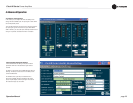
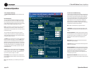
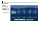
Continuous Load Monitoring
The load supervision feature allows real-time monitoring of the
load connected to each amplifi er channel. When enabled, the I-
Tech contin uously monitors the amplifi er output voltage and
current, and calcu lates the long-term average load impedance.
The measured load impedance is compared against the user-
defi ned high and low limits. If either limit is exceeded, the
status indicator and, if enabled, the System Architect Error
Reporting functions alert the user of the problem. There are six
controls and two indicators for each channel:
On: Enables or disables the load-supervision function.
Load Status: This indicator shows the present sta tus of the
load impedance with respect to the user-defi ned high and low
limits.
Average Impedance: Sets the expected average impedance
for the connected load. This value determines the output signal
level required for the test. This parameter is also used by the
average power limiter to determine the expected power
threshold.
High Limit: Sets the upper bound above which the system
will report a “high” error status.
Low Limit: Sets the lower bound below which the system will
report a “low” error status.
Average Impedance: Sets the expected average impedance
for the connected load. This value determines the output signal
level required for the test. This parameter is also used by the
average power limiter to determine the expected power
threshold. You set this fi eld to the nominal impedance of the
connected load per channel.
Report Errors via Network: When this is turned on, high
and low load errors are sent via the network to System Architect
software.
4 Advanced Operation