


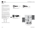
Operation Manual
I-Tech HD Series Power Amplifi ers
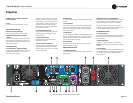
page 12
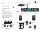
3 Operation
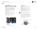
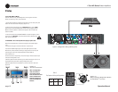
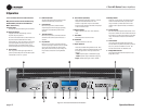
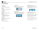
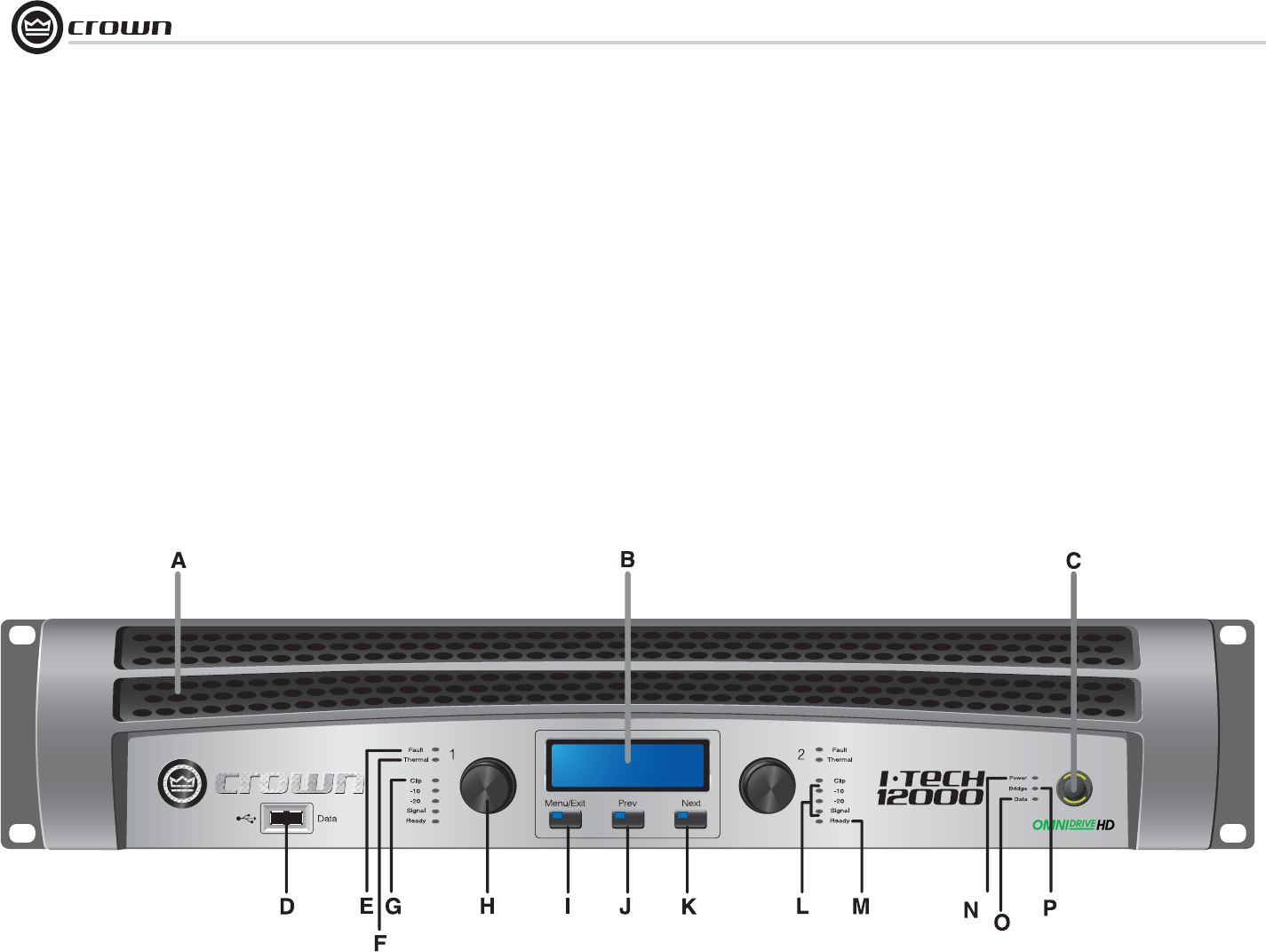
Figure 3.1 Front Panel Controls and Indicators
3.4 Front Panel Controls and Indicators
Many of these functions can be disabled using
Blackout Mode (a selection in the Advanced
Menu, Section 4.2.3).
A. Cooling Vents
Front-to-rear forced airfl ow through foam dust fi lter
B. LCD Control Screen
Integrated LCD with white backlight, controls
ampli fi er setup and operation.
The LCD Control Screen and its controls let the user
adjust the amplifi er’s attenuation and muting,
con fi gure the amp, set up and view error monitoring
(such as temperature and load supervision), and
recall DSP presets. The presets allow the user to
quickly reconfi gure the amp for various applica tions.
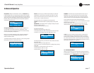
C. Power Switch
Push-on/push-off switch glows green when AC
power is present at the power cord and the amplifi er
circuit breaker is in the “on” position.
D. USB 2.0 Connector
Accepts a USB drive to transfer presets from the
drive to the amplifi er DSP, and vice versa.
E. Fault Indicator
Red LED, one per channel, fl ashes when the
ampli fi er output channel has stopped operating.
Usually this means that the amplifi er must be
serviced.
F. Thermal Indicator
Red LED, one per channel, illuminates when the
channel has shut down due to thermal stress or
overload.
G. Clip Indicator
Red LED, one per channel, illuminates when the
channel’s output signal reaches the onset of audible
clipping. The Clip Indicator also will illuminate
dur ing Thermal Level Control (TLC) limiting. The
Clip Indicator can be turned of during Blackout
mode.
H. Level Controls (Encoders)
Speed-sensitive, 0.5 dB steps, range 0 to –100 dB.
These two knobs affect the Channel-1 and
Channel-2 output levels. They also select Menu
items and adjust parameter values that are displayed
on the LCD control screen.
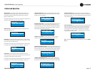
I. Menu/Exit Button
“Menu” enters the main menu. “Exit” leaves the
menu.
J. Prev Button
Selects the previous item in the menu.
K. Next Button
Selects the next item in the menu.
L. Signal Indicators
These can be disabled during Blackout mode. Three
green LEDS per channel indicate the ampli fi er’s input
and output signal levels. From top to bot tom the
LEDs are
–10 dB: amplifi er output is 10 dB below clipping.
–20 dB: amplifi er output is 20 dB below clipping.
Signal: selected input signal is above –40 dBu.
M. Ready Indicator
Green LED, one per channel, illuminates when the
channel is initialized and ready to produce audio
out put. Indicator is off when the channel is set to
standby mode via System Architect or in Blackout
mode.
N. Power Indicator
Blue LED indicates amplifi er has been turned on and
AC power is available. The LED will fl ash when the AC
line voltage is 15% above or below the nominal rated
range. This indicator can be turned off in Blackout
mode.
O. Data Indicator
Yellow LED indicates network data activity. Data
indicator fl ashes only when the amplifi er is polled for
data, or is polled to see whether it is online. This
indicator can be turned off in Blackout mode.
P Bridge Mode Indicator
Yellow LED illuminates when the amplifi er is set to
Bridge-Mono mode.