


I-Tech HD Series Power Amplifi ers
Operation Manual
page 19
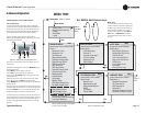
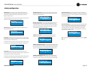
Pink Noise Generator: Press an Encoder knob to turn on the generator. Its
level will read –100 dB. Adjust the noise level from –100 dB to +20 dB in 0.5 dB
steps by turning Encoder 1 or 2. To turn off the generator, press an Encoder knob
or go to another menu item.
Exit: To exit the Advanced Menu and go to the Attenuation screen, press Menu/
Exit once.
LevelMax - RMS Voltage Limiter: Limits the output rms voltage to an
amount that you set, either OFF or 1 to 500 volts, for each channel. Press the
Encoder to turn on the Limiter. Once it’s on, turn the Encoder to set the voltage.
Input Delay: Sets the input signal delay in each channel. Turn each channel’s
Encoder knob to vary the delay. The delay step size is speed sensitive. Pressing
the encoder enables or disables the Delay.
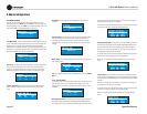
Below each channel’s delay setting is the equivalent distance in feet and meters.
For example, 10 ms is the signal delay of sound traveling 11.3 feet or 3.4 m.
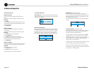
Output Polarity: Press each channel’s Encoder knob to toggle the output
signal polarity between + and –.
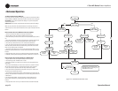
Bandpass Gain: In each channel of the I-Tech HD’s DSP, just before the
output limiter and after the preceding fi lter, is a gain block (not shown on the
Signal Path block diagram). Bandpass Gain adjusts the gain of this block
between -24 dB and +24 dB.
Adjusting the bandpass gain in the LCD screen makes it easy to vary the level of
subwoofers, midrange drivers and high-frequency driv ers.
Front Panel Blackout: This screen lets you black out the front panel display
unless you press a front-panel button or turn an Encoder. This feature turns
off the LCD backlight and all front panel LEDs except for the fault LEDs and
power-switch green LED. After blackout is enabled, an Encoder press/turn
will “reactivate” the display. If no button is pressed/turned for 5 seconds, the
display will return to blackout mode.
0.0
Bandpass Gain
Bandpass Gain
0.0
dB
+
Output Polarity
Output Polarity
+
Press enc to toggle
0.0000
Input Delay
Input Delay
0.0/0.0
0.0000
0.0/0.0
ms
ft/m
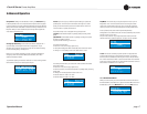
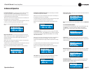
Output Delay: Sets the output signal delay in each channel. Turn each
channel’s Encoder knob to vary the delay. The delay step size is speed sensitive.
Pressing the encoder enables or disables the Delay.
Below each channel’s delay setting is the equivalent distance in feet and meters.
For example, 10 ms is the signal delay of sound traveling 11.3 feet or 3.4 m.
0.0000
Speaker Delay
Speaker Delay
0.0/0.0
0.0000
0.0/0.0
ms
ft/m
LED Meter Display Type : Here you can set the LCD bar meters to display
average or peak levels. Turn an Encoder knob to select the option, then press
the knob to confi rm your selection.
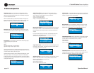
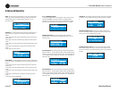
Bar Meter Display Type: You can select what the bar meters will display in
the Attenuator Screen. Press an Encoder knob to select Attenuation, Input
Levels, Output Levels, or Thermal %. Attenuation is displayed as the length of
the bar meters in the Atten uation screen that appears on startup. The meters
display average input levels and output levels.
ATTENUTATION
Bar Meter Display Type
Bar Meter Display Type
Turn to Set-Press to Save
LevelMax- Peak Voltage Limiter: Limits the peak output voltage to a level
that you set, either OFF or 1 to 500 volts, for each channel. Press an Encoder to
turn on the Limiter. Once it’s on, turn the Encoder to set the voltage. Additional
controls, such as attack and release, are available through System Architect.
LevelMax - Clip Limiter: Limits the peak output voltage to just below
clipping for each channel. Press an Encoder knob to turn it OFF or ON.
OFF
Clip Limiter
Clip Limiter
OFF
OFF
Peak Voltage Limiter
Peak Voltage Limiter
OFF
v
v
OFF
RMS Voltage Limiter
RMS Voltage Limiter
OFF
v
v
OFF
Pink Noise Generator
Pink Noise Generator
OFF
dB
dB
4 Advanced Operation
OFF
Front Panel Blackout
Front Panel Blackout
AVERAGE
LED Meter Display Type
LED Meter Display Type
Turn to Set-Press to Save