


2
INSPECTION AND ACCESSORIES
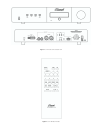
The Classé CT-10 has been carefully wrapped in
heavy gauge plastic, packed in semi-rigid foam
and contained in a special box. Inspect the unit
and accessories for any concealed damage.
Report any concealed damage to your dealer
promptly.
Apart from the owner's manual, please ensure
the following is also included:
• Detachable A.C. power cord.
• Remote control handset (along with two (2)
type “AAA” batteries).
Please report any missing parts to your dealer
promptly and bring him/her (or fax him/her) the
inspection report found in the box.
SETUP
The CT-10 TUNER must be operated on a
horizontal platform (see specifications for details)
such as a table or, preferably, specialized audio
furniture to extract the best performance. Like
fine turntables and interconnect cables, the final
location of the CT-10 should be free of any hum-
inducing magnetic fields, such as those caused
by power amplifiers, AC line filters and other
regulation devices. Such locations can introduce
noise into an audio system, which inevitably
degrades sound quality. Ideally, a few feet should
separate the CT-10 from the power amplifier.
The CT-10 should not be located near a CD or
DVD player since this can cause reception
problems. Keep low-level interconnect cables
away from the power amp and separate from
A.C. power cords. The CT-10 generates negligible
amounts of heat. Therefore, air space around the
CT-10 for ventilation need not be a concern.
AUDIO CONNECTIONS
Connect your tuner to the pre-amplifier, using
cables/interconnects in your system. For a single-
ended (un-balanced) system the cables will be
connected to the RCA on the rear panel of your
tuner to an unused line level input on the rear of
your pre-amplifier/integrated amplifier. For
connection to a balanced system, the balanced
cables will be connected to the XLR outputs
marked “Balanced” on the rear of your tuner to
the balanced inputs on the rear of your pre-
amplifier or integrated amplifier. For visual aid,
use figure 1.
ANTENNA CONNECTION
Connect your FM antenna cable to the ANTENNA
terminal on the rear panel of the tuner. The
connection type on back of your tuner is an “F”
connector (75 ohms). Should your antenna cable
be 300 ohm twin lead, you may convert this to
75 ohms with a 300 ohm to 75 ohm balun/
transformer.
Make sure that the center conductor of the cable
is properly inserted into the connector.
PLEASE NOTE: Many countries that use 220/230
and 240 volts use FM transmitters with special
tuning emphasis. Tuning de-emphasis required
from the CT-10 in these countries may be
different. Please consult your Classé Audio Dealer
or Distributor for the correct usage. If your tuner
is used in a country where the tuning de-
emphasis is set incorrectly the sonic performance
will be seriously affected.
You will need to connect different antennas for
both FM and AM reception. Refer to the
Reception and Performance Information
section for detailed information regarding
antennas.
FM ANTENNA
An FM “dipole” antenna is a pink-hued flexible
wire that looks like a “T” when it’s stretched out.
This is a good antenna for system setup and
evaluation, however it has limitations to overall
performance, and a higher quality antenna
system is recommended. Please see the reception
and performance information section of this
manual for further details on selecting the
antenna system best suited to your needs.
To connect:
• Use a screwdriver to loosen the two screw
terminals on the adapter.
• Slide one of the metal spade lugs under each
screw terminal.
• Tighten the screw terminals so the spade lugs
are firmly secured and not touching each
other.
• Slide the balun adapter onto the threaded
round antenna connector on the CT-10.
• Position the antenna for best FM reception.
• Fasten the antenna on the wall or behind the
equipment cabinet.
AM ANTENNA CONNECTION
For AM reception, you will need a separate
molded plastic loop AM antenna with spade lugs
at the end of its two wires. With this antenna,
you can receive AM stations in many urban and
suburban locations. Please see footnote on
maximizing AM performance on this page.
To connect:
• Loosen the two AM terminals on the CT-10
rear panel. No screwdriver is needed.
• Slide the spade lug from each antenna wire
under one of the AM terminals.
• Tighten these terminals so the spade lugs are
firmly secured and not touching each other.
• Position the loop antenna as far away from
the CT-10 as possible to minimize its
interference with the AM section for best AM
reception.
PLEASE NOTE: The AM antenna can be mounted
to the rear chassis of the CT-10. This is done for
convenience but requires careful positioning to
avoid interference. If you are unable to eliminate
any antenna interference, mount the AM loop
antenna as far away from the tuner and any
metal surface as the provided cable will permit.
USING THE CT-10 WITH INFRARED
REPEATER SYSTEMS
EXTERNAL REMOTE INPUT AND LOOP OUT
The IR input allows for infrared remote control
operation via a wired infrared repeater system or
system controller when infrared commands
cannot directly reach the front panel infrared
receiver. This input connector accepts a standard
1/8-inch (3.5 mm) two conductor mono mini
plug. The tip is positive and the sleeve is
negative. Your Authorized local Classé Audio,
Dealer or Custom Installer can recommend a
compatible infrared repeater system for the
CT-10. The External remote circuit has a loop
output so you can connect additional IR
controlled devices.
CONNECTION OF INFRARED REPEATER
The IR In jack is for a wired infrared repeater
system or system controller. It eliminates the
need for a stick-on front panel IR flasher. For this
purpose, you will need to acquire the following
accessories:
• An infrared receiving eye.
• A power supply for the IR system.
• A connecting block from the external IR
system’s manufacturer.
• One cable with 1/8” mini mono plugs at both
ends.
To connect:
• Plug the receiving eye into the input on the
connecting block.
• Plug the power supply into the connecting
block.
• Push one of the cable’s 1/8” mini-plugs into
the connecting block.
• Push the other end of this cable into the IR In
jack on the CT-10.
• Plug an IR flasher or other IR repeater into
the CT-10’s IR Out jack to control another
component if desired.
PLEASE NOTE: IR repeater connections may vary
by brand. Refer to the installation manual of your
IR repeater system for more information.
DC TRIGGERING
The CT-10 can be turned on or off automatically
with a 12 VDC trigger from an external DC
voltage source such as a preamplifier or system
controller.
For this purpose, you will need to acquire the
following accessories:
• A trigger cable with 2.5 mm sub-mini plugs.
• A component with an external +9VDC to
+12VDC trigger voltage.
Before Connecting, make sure to turn off the
power to the CT-10.
To connect, insert one end of this cable into the
12V Trigger In jack on the CT-10.
Plug the other end into the device with an
external DC trigger voltage.