


27 Sp
Funcionamiento de
la herramienta
(continuación)
Soporte magnético para tornillos
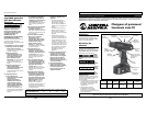
Este taladro/destornillador está
equipado con un imán en la parte
superior del mismo, debajo del símbolo
de imán en herradura. Esto es útil para
guardar tornillos cuando se realiza un
trabajo repetitivo.
Luces indicadoras del medidor de
carga de la batería
Este taladro/destornillador está
equipado con un medidor de carga de
la batería. Está ubicado en la parte
superior del taladro y se compone de
tres luces verdes y un botón negro.
Para verificar el estado de la batería,
presione el botón negro cuando el
taladro esté apagado. Si se iluminan
las tres luces verdes, esto indica una
batería con carga completa o casi
completa. Si solo se ilumina una luz
verde, la batería está próxima al punto
en el que debería recargarse. Si no se
ilumina ninguna luz, la batería
necesita ser recargada.
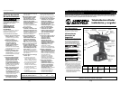
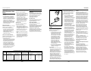
Colocación / remoción de brocas
• Para fijar la broca en el taladro,
mueva el botón de avance y
retroceso (FWD/REV) a su posición
central y gire el anillo de embrague
hasta el símbolo de broca del
taladro. Gire el manguito del
portabrocas hacia la izquierda
(mirando desde el extremo del
portabrocas) hasta que las mordazas
del portabrocas se abran un poco
más que el diámetro de la broca a
colocar. Coloque una broca limpia
hasta las estrías de la broca (para
brocas más pequeñas) o hasta donde
llegue para brocas grandes. Cierre el
portabrocas girando el manguito
hacia la derecha y ajuste a mano en
forma segura.
• Para quitar la broca del taladro,
mueva el botón de avance y
retroceso (FWD/REV) a su posición
central y gire el anillo de embrague
hasta el símbolo de broca del
taladro. Gire el manguito del
portabrocas hacia la derecha
(mirando desde el extremo del
portabrocas) hasta que las mordazas
del portabrocas se abran un poco
más que el diámetro de la broca
y luego retire la broca.
No use la corriente del taladro
para aflojar ni ajustar la broca
mientras sostiene el portabrocas.
Al girar, el portabrocas causará
quemaduras por fricción y lesiones
en la mano.
Con este taladro se incluyen
incorporadas puntas de destornillador
Phillips o de paleta y se pueden
instalar fácilmente como se explicó
anteriormente. Éstas son
particularmente útiles para atornillar
y quitar tornillos.
Instrucciones
generales de
taladrado
Se
deberán
usar gafas de seguridad durante
las operaciones de taladrado.
Siempre esté atento y contrarreste
la acción giratoria del taladro.
Cuando se taladre siempre debe
usarse un asimiento firme. El no
hacerlo podría ocasionarle lesiones
corporales.
• Ajuste el collar del portabrocas del
taladro de modo que la flecha en el
cuerpo del taladro apunte hacia el
símbolo de la broca en el collar del
portabrocas.
• Ajuste el selector de velocidad a la
velocidad deseada. Generalmente
cuanto más duro sea el material a
taladrar, más lenta es la velocidad
recomendada.
• Asegúrese de que la broca del
taladro esté fijada con seguridad en
el portabrocas.
• Asegúrese de que el botón de
avance (FWD) esté totalmente
presionado. Esto hará que el taladro
gire en la dirección de avance, es
decir, hacia la derecha cuando se
mira desde el punto de vista del
usuario.
•
Asegúrese de que la pieza de
trabajo esté asegurada. Esto
puede implicar sujetarla en una
prensa o sostenerla con
seguridad por otro medio de
sujeción. Una pieza de trabajo
floja puede girar y causar
lesiones corporales.
• Ubique el centro del orificio a
taladrar y usando un punzón, haga
una pequeña muesca en la pieza de
trabajo.
• Coloque la punta de la broca del
taladro en esta marca, sostenga el
taladro perpendicular a la pieza de
trabajo, aplique una presión
constante y accione el interruptor
del taladro.
•
Continúe aplicando una presión
firme y pareja mientras taladra.
El aplicar demasiada presión
puede causar que la broca se
recaliente y/o se quiebre, lo cual
podría provocar lesiones
corporales o daños a las brocas.
Una presión demasiado suave
evitará que la broca perfore la
pieza de trabajo.
• Si el taladro pierde sustentación o se
atasca en el orificio, suelte el gatillo
de inmediato. No continúe
accionando el gatillo en la dirección
de avance para liberar la broca
atascada, ya que esto dañará el
motor. Quite la broca de la pieza de
trabajo y determine la causa de la
pérdida de sustentación o
atascamiento antes de volver a
comenzar. Si se dificulta la remoción
de la broca de la pieza de trabajo,
entonces presione totalmente el
botón de retroceso (REV) y accione
el interruptor para quitar la broca.
Luego presione totalmente el botón
de avance (FWD) antes de retomar el
trabajo de taladrado.
• Cuando la broca esté a punto de
salir por el otro lado del material
que se está taladrando, reduzca la
presión sobre el taladro para evitar
astillar la madera o que pierda
sustentación en una pieza de trabajo
de metal.
DG201900CK
Tool Operation
(Continued)
Two-speed gearing
In addition to the variable-speed
switch, this drill is also equipped with a
two-speed gearbox. The low gear
(setting “1”) provides high-torque and
slower drilling speeds for heavy-duty
work or for driving screws. The high
gear (setting “2”) provides faster
speeds which is particularly useful for
drilling into softer materials. To
change to the high-speed setting, push
the (red) speed selector knob fully
forward. For the low-speed setting,
move the speed-selector knob fully
toward the rear of the drill. It is
important that this knob be positioned
fully forward or fully back, anywhere
in between can cause damage to the
drill.
If the drill has been actuated but the
chuck is not rotating, fully release
pressure on the switch actuator and
then slide the gear actuator to its
desired setting.
Electrical Brake
This drill is equipped with an electrical
brake which is used to stop the chuck
quickly. This is useful when the job
calls for repetitive driving or removal
of screws. This is activated by merely
releasing the switch actuator while the
drill is rotating. When the electric
brake is actuated, it is common to see
momentary arcing within the drill
itself.
Adjustable Clutch
This drill/driver features 16 clutch
settings. Output torque will increase as
the clutch collar is rotated from 1 to
15. The drill bit position locks the
clutch in order to permit heavy-duty
drilling and driving work. It also allows
bits to be changed quickly and easily in
the keyless chuck. This adjustable
clutch is particularly useful when
driving screws. A lower clutch setting
will ratchet sooner than a high-clutch
setting, that is, it will limit how far a
screw is driven. When driving screws, it
is best to start at a lower clutch setting
and adjust this collar upwards until the
screw is set to the desired depth.
Bubble Levels
This drill/driver is equipped with two
bubble levels in order to make it easier
for the user to drill squarely. There is a
horizontal level on top of the drill and
in order to drill/drive horizontally, the
bubble on this particular level should
be centered between the two level
lines. For those jobs where the user
wants to drill straight up-and-down,
there is another level on the back side
of the drill for that particular purpose.
For vertical drilling, the center of the
bubble should be at the intersection of
the crosshairs.
Magnetic Screw Holder
This drill/driver is equipped with a
magnet on top of the drill, underneath
the horseshoe magnet symbol. This is
useful for storing screws when doing
repetitive work.
Battery Fuel Gauge Indicator Lights
This drill/driver is equipped with a
battery fuel gauge. This is positioned
on top of the drill and is composed of
three green lights and a black button.
In order to check the state of the
battery pack, depress the black button
when the drill is OFF. If three of the
green lights illuminate, this indicates a
fully-charged or nearly charged
battery pack. If only one green light
illuminates, the battery pack is nearing
that point where it should be
recharged. If no lights illuminate, the
battery pack needs to be recharged.
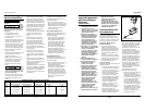
Inserting / Removing Bits
• In order to clamp a bit in the drill,
move the FWD/REV button to its
center position and rotate the clutch
ring to the drill bit symbol. Rotate
the chuck sleeve counterclockwise
(when viewing from the chuck end)
until the chuck jaws are opened
slightly more than the diameter of
the bit to be inserted. Insert a clean
bit up to the drill bit flutes (for
smaller bits) or as far as it will go for
large bits. Close the chuck by
rotating the chuck sleeve clockwise
and securely tighten by hand.
• In order to remove the bit from the
drill, move the FWD/REV button to
its center position and rotate the
clutch ring to the drill bit symbol.
Rotate the chuck sleeve clockwise
(when viewing from the chuck end)
until the chuck jaws are opened
slightly more than the diameter of
the bit and then remove the bit.
Do not
use the
power of the drill to loosen or tighten
the bit while holding the chuck. The
spinning chuck will cause friction burn
and hand injury.
Phillips and slotted screw driver bits
are included onboard with this drill
and can be easily installed as
previously noted. These are particularly
useful for driving/removing screws.
General Drilling
Instructions
Safety
glasses
must be worn during drilling
operations.
Always
be alert
and brace yourself against the twisting
action of the drill. A firm hold should
always be administered when drilling.
Failure to do so may result in bodily
injury.
• Adjust the drill’s chuck collar so that
arrow on the drill body points to the
drill bit symbol on the chuck collar.
• Set the speed selector to the desired
setting. Typically the harder the
material being drilled into, the
slower the recommended speed.
• Insure that the drill bit is securely
gripped in the chuck.
• Make sure that the FWD button is
fully depressed. This should make
the drill rotate in the forward
direction, that is, clockwise as
viewed from the user’s vantage
point.
6
Operating Instructions