


640Razur
9
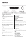
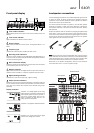
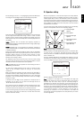
Front panel display
Tuner mode indicators
Shows Memory/Store active, Stereo mode active, AutoScan active and
RDS On.
Tone control indicator
Lights when Bass and Treble controls are active.
Direct indicator
Lights when the 640R is in a Direct mode - Analog Stereo Direct or 7.1
Direct.
Frequency type
Indicates the tuned frequency in AM or FM Tuner mode.
Decoding mode indicators
Shows the current decoding mode, Dolby Digital, Dolby Digital EX etc. In
conjunction with the Output Channel indicators these give full details of
the current processing mode.
Main information display
Shows the current source selected, also the surround mode and station
name/frequency when in tuner mode etc.
Balance indicator
Lights when the Front Left and Right speaker outputs have been set to
different levels in the OSD, i.e. a balance adjustment has been made.
Digital/Analog indicators
Indicates the current source input type - digital or analog.
Output channel indicators
Shows the currently active channels depending on decoding mode and
source material. Icons lit indicate active channels in the source material.
Icons with a box around them indicate actual channels being output
separately.
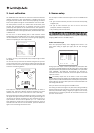
Display examples
- Indicates a 5.1 Dolby Digital source being
played back as 5.0 (Sub off). LFE indicates a
low frequency effects channel is present in
the source material. When this icon isn’t
boxed it indicates the LFE channel is not
being reproduced separately.
- Indicates a 7.1 playback of DTS ES material.
- Indicates a 2.1 output created in the digital
domain from analog input material.
1
2
3
4
5
6
7
8
9
2 31
6
7 8 9
4 5
ENGLISH
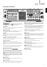
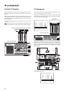
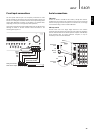
To avoid damaging the speakers with a sudden high-level signal, be sure
to switch the power off before connecting the speakers. Check the
impedance of your speakers. Speakers with an impedance of between
4 and 8 ohms (each) are recommended.
The coloured speaker terminals are positive (+) and the black speaker
terminals are negative (-). Make sure correct polarity is maintained at
each speaker connector or the sound can become weak and “phasey”
with little bass.
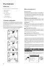
Prepare the speaker cords for connection by stripping off approximately
10mm (3/8”) or less (no more than 10mm, as this could cause a short-
circuit) of the outer insulation. Twist the wire tightly together so there are
no loose ends. Unscrew the speaker terminal knob, insert the speaker
cable, tighten the knob and secure the cable.
Note:
All connections are made via loudspeaker cable, except if using an
active subwoofer which would be connected via a standard RCA phono
cable. Banana Plugs (4mm standard) connected to the speaker cable
are recommended for direct insertion into the speaker terminals.
Please refer to the ‘Speaker Configuration’ section of this manual for
more information on 5.1, 6.1 and 7.1 speaker setups.
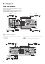
Loudspeaker connections
V Receiver
Front
Right
Front
Left
Surround
Left
Surround
Back Left/
Surround Back
Centre
Surround
Right
Surround
Back Right
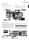
Control
Bus
InIn
Emitter
OutIR1 IR2
PSU 24V DC In
IR3
12
Keypad 1 Keypad 2
DVD
SR
SBR
SW
L
SL
SBL/SB
Y
Cb/Pb
Cr/Pr
Y
Cb/Pb
Cr/Pr
Y
Cb/Pb
Cr/Pr
Y
Cb/Pb
Cr/Pr
C
7.1 Direct In 7.1 Preamp Out
Serial No. label fitted on underside
Max Power Consumption: 1400W
Power Rating: 230V AC 50Hz
R
SR
SBR
L
SL
SBL/SB
CR
TV/Mon Out
Video 1
Video 2
Speaker Impedance 4-8 Ohms
Multi-Room
Video Out
This device complies with
part 15 of FCC rules
Power AC
Power
On
Off
Manufactured in an
ISO9002 approved facility
tric shock. Do not open. Do not obstruct ventilation.
ectrique. Ne pas ouvrir. Ne pas obstruer la ventilation.
gërates. Netzstecker ziehen. Ventilation nicht verschließen.
Designed in London, England
w.cambridge-audio.com
International Patent Pending LeisureTech Electronics Pty Ltd
7.1 6.1 5.1
SW
Use
approved
PSU only
Component
Recorder 1
Front
speakers
Surround
speakers
Centre speaker
Surround back
speakers
Powered subwoofer
Phono/RCA cable