


Operation
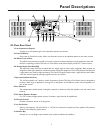
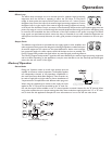
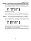
Effects Loop
The effects loop connectors act as an insertion point for outboard signal processing
equipment when the M-Class is operating in either the 70V Mono or Dual Mono
modes. In these modes, the inputs and front panel controls form a 2:1 mixer. Connect
the Effects Loop Out to the input of the external signal processing equipment.Connect
the Effects Loop In to the output of the external signal processing equipment. Inserting
an RCA jack into the Effects Loop In connector will automatically disconnect the input module signals from the
power amp stage so it can be routed through the external equipment. Removing the jack from the Effects Loop
In connector will reestablish the direct connection of the input modules to the power amp stage.The Effects
Loop signals are quasi-balanced, which means that they are intended for use with unbalanced equipment but
will improve the noise immunity. However, it is still a good practice to keep these connections as short as pos-
sible.
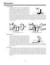
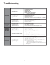
Output Feeds
Two different output feeds are provided that can supply signal to other amplifiers and
audio equipment.Both outputs are designed to feed high-impedance, unbalanced inputs
of external equipment.The outputs are also quasi-balanced for better noise immunity,
but connection lengths for these outputs should still be kept as short as possible.The
Pre-EQ Output Feed provides the signal before any external signal processing affects it.
The Post-EQ Output Feed provides a signal that has been affected by the external signal processing equipment
and lo-cut filter. Depending on the application, it may be more desirable to use the externally-processed signal
rather than the raw version of the signal.
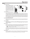
Modes of Operation
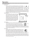
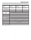
Stereo Mode
Placing the 3-position switch to its left most position puts the
amplifier in the stereo mode of operation.The amplifier supplies
two independent channels of low-impedance amplification in
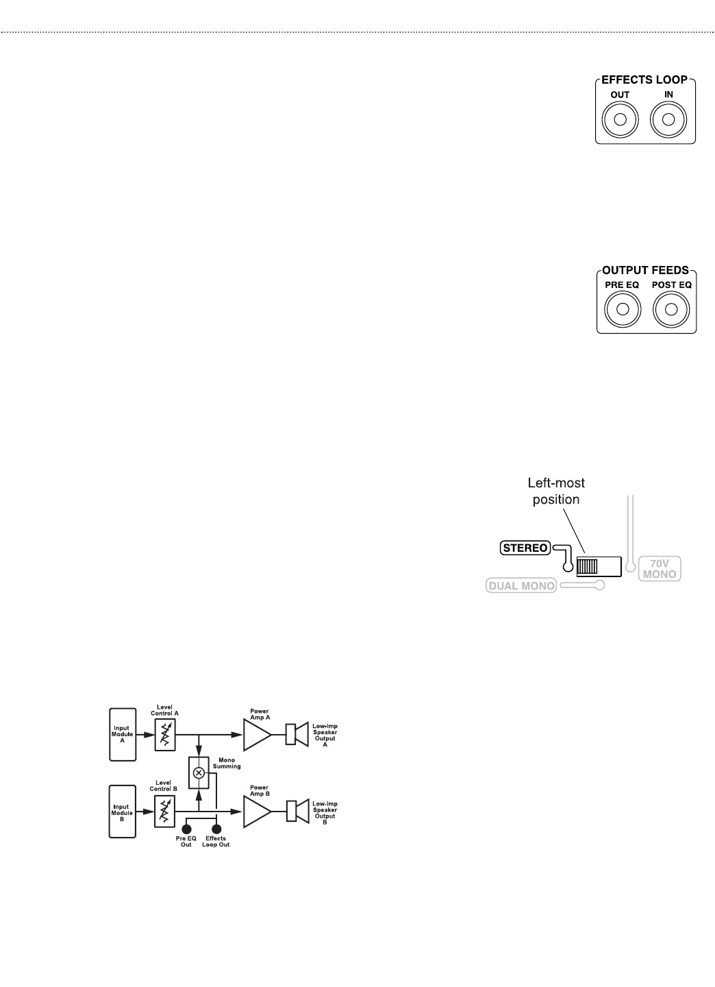
this mode (see Stereo Mode Block Diagram).These channels can
be used to supply left and right audio for stereo installations of
2 separate zones of amplification with different audio programs.
When using the supplied input module in this mode, the input
applied to the "A" input will be controlled by the "A" level con-
trol and the output will be available on the "A" channel speaker terminals. Likewise for the "B" channel.When
using other modules, there are jumper settings that allow those modules to apply signal to the "A" or "B" chan-
nels, or both. See the application examples for more information on how to use the two audio buses.
9
Stereo Mode Block Diagram