


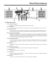
Connections
Speakers
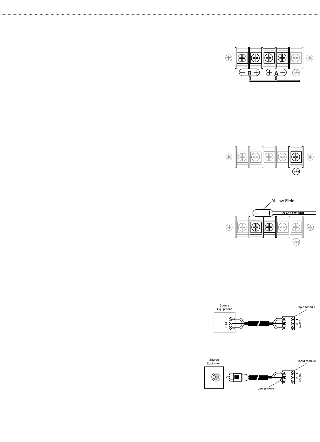
Low-Impedance Speaker Connections
When the amplifier is set to either the stereo mode or the Dual
Mono mode (see Operation section), low-impedance speakers can be
connected to either the "A" or "B" speaker output terminals. The
amplifier is designed to work into speaker load impedances as low as
3.2 ohms.
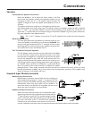
The speaker terminals can accept up to a #10 spade lug and have inte-
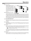
gral clamping plates which make wiring easier.The polarity of each set of speaker outputs (A & B) is indicated
with a "+" and "-" sign. Use these indicators to ensure that the phasing of the speakers are correct. Do not
ground the "+" output of either set of outputs.Doing so will cause the amplifier to go into protect mode, shut-
ting down operation of the affected channel.
Note: The "+" and "-" indicators are mirrored on "A" and "B" outputs. Be sure to make the correct connections.
Earth Ground Terminal
The earth ground terminal is provided as a convenient means to con-
nect to the amplifier’s chassis/AC ground,if necessary. DO NOT con-
nect the earth ground terminal to the "+" terminals of either output.
No damage will occur if this is done, but the amplifier will go into pro-
tect mode and shut down the effected channel.
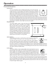
70V "Transformer-Coupled" Speakers
The 70V speaker output terminals are only usable when the amplifier
is in the 70V Mono mode (see the Operation section). In this mode,
both channels are bridged into a single mono channel.Use only speak-
ers that are designed to work with 70V audio systems when con-
necting to these terminals.The speaker terminals can accept up to a
#10 ring lug and have integral clamping plates which make wiring eas-
ier. The 70V output terminals are indicated by a yellow field above
them. The polarity of the output terminals is indicated for speaker
phasing purposes. These output terminals must float and cannot be referenced to earth ground, so if they
become grounded, the amplifier will go into protect mode, shutting down operation of the amplifier even
though no damage to the amplifier will occur.
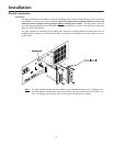
Standard Input Module (included)
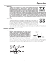
Balanced Input Connections
Balanced input connections are used when the source device pro-
vides a balanced output (signal "+", signal "-",and ground "G").This
type of connection is desirable when operating in electrically noisy
environments, where long input cable runs are needed, or to
ensure the lowest noise operation. If compatible with the source
device, this type of connection is recommended.
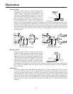
Unbalanced Input Connections
When the source device provides only an unbalanced output
(signal and ground),the input module should be wired with the
"-" input shorted to ground (G).The unbalanced signal's shield
wire is connected to the input module’s ground and the signal
hot wire is connected to the "+" terminal. Since unbalanced
connections do not provide the same amount of noise immu-
nity that a balanced connection does, the connection distances should be made as short as possible.
7