


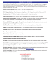
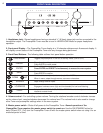
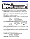
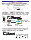
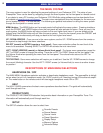
The Preamplifier Tuner's back panel is organized into groups of inputs and outputs as shown above.
1. AC Input Receptacle - For attaching the supplied AC power cord to the Preamplifier Tuner. The
serial number of your unit is located below the AC input receptacle. AC line fuse rating - .5A 250V
2. RS-232 - RS-232 Two Way communication allows enhanced system control and BKcSuite inter-
face.
3. IR output - IR signals received by your Preamplifier's front panel or the Infrared Data/Signal input
pin are repeated out this IR connector 1/8” (3.5mm) mono.
4. Control I/O - Allows connections to a zone keypad/IR sensor via a 5 pin plug-in Phoenix connector. Also
supplies a control voltage for an amplifier.
+12V - +12VDC Power to Keypad or IR Sensor
Ground - Common Ground
RS-232 Xmit - RS-232 One Way Transmit Out
Data In - Infrared Data Input
CTRL Out - 12VDC Programmable Control Out
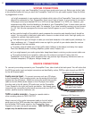
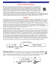
5. FULL RANGE Balanced (XLR) output - Variable preamp outputs for driving an external power
amplifier.
Pin 1 - ground
Pin 2 - POS +
Pin 3 - NEG -
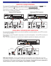
6. MONO L+R and SUB PREAMP (RCA) outputs - Variable level outputs for driving external power
amplifiers or powered speakers. Mono is the summation of the L+R full range audio signals. It is then
processed by a low-pass filter to reduce audio above 80 Hz to source the SUB output.
7. HIGH PASS (RCA) output - Variable preamp outputs for driving external power amplifiers or pow-
ered speakers.
These outputs have been processed through a high pass filter to reduce audio below
80 Hz. Use these output
s for small speakers or in a subwoofer / satellite system. Note: these output
s
are identical to the full range outputs with the addition of an 80 Hz 12 dB / Octave high-pass filter.
8. FULL
RANGE (RCA) output -
V
ariable preamp outputs for driving external power amplifiers.
9. TAPE inputs and output - Line level input and fixed output for use with an audio recorder. Tape
Output supplies a return loop for the source input selected.
10. Source line input
s -
Lef
t and right connections from your audio sources.
Red RCA jacks = Right analog audio
White RCA
jacks = Lef
t analog audio
11. Antenna inputs - Connections for the AM and FM antennas.
5
BACK PANEL DESCRIPTION
V1V2TV
SOURCE INPUTS
DVD
CD
INPUT
OUTPUT
T
APE
PREAMP OUTPUTS
FULL
RANGE
HIGH
PASS
S
UB
M
ONO
L+R
Audio/Video Systems Hand-Made in the U.S.A.
BK
&
SB
IMPLY ETTER!
R
ISKOFELECTRICSHOCK
DONOTOPEN
CAUTION
A
NTENNA
AM
F
M
V
OLTAGE
RS-232
IR
OUTPUT
BALANCEDOUTPUT
FULLRANGE
L
EFT
R
IGHT
S
ERIAL #
G
R
O
U
N
D
R
S
2
3
2
T
R
A
N
S
M
I
T
I
R
D
A
T
A
I
N
P
U
T
C
O
N
T
R
O
L
O
U
T
+
1
2
V
A
C LINE
2
00 mA Max
C
urrent @ 12V
1 2 3 4 5 6 7 8 9 10 11
22
11
3
3
PIN1(GND)PIN1 (GND)
PIN3(-)PIN3 (-)
PIN2(+)PIN
2(+)
BalancedInterconnectCable
12
3
PIN1(GND)PIN1 (GND)
PIN3(-)PIN
3(-)
PIN2(+)PIN
2(+)
PreamplifierBalancedOutputConnector