


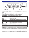
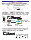
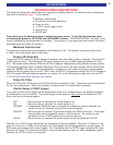
FIVE POSITION PHOENIX CONNECTOR
Control I/O - The five pin phoenix connector can be used when interfacing other equipment with the
Reference 5 S2. Equipment such as CK1.2 Keypads, an external amplifier, or devices that require a +12VDC
trigger.
+12VDC - +12VDC power supply for keypad or IR sensor
Ground - Common ground
RS-232 Xmit - RS-232 one-way transmit out
Data In - Infrared Data/Signal input
CTRL Out - 12VDC programmable trigger out
Note - The entire control output is capable of suppling a maximum
of 12VDC @ 200 mA. Check to see
that the device(s) being connected to the control require 200 mA or less current.
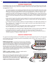
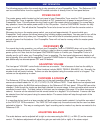
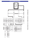
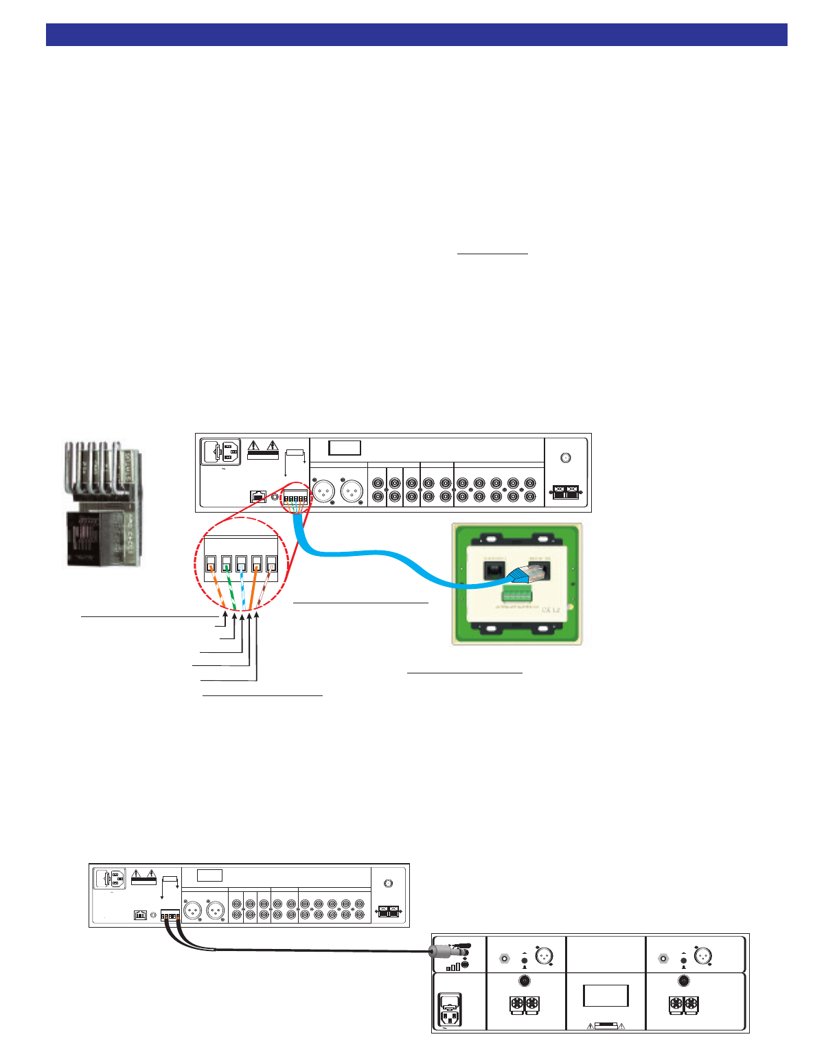
KEYPAD or IR SENSOR CONNECTION
To connect a CK1.2 Keypad to the Reference 5 S2, simply run a straight through CAT5 wire from the keypad
location to the Reference 5 S2. The keypad end of the CAT5 can be terminated into RJ-45. The keypad end
can also be terminated into the five position phoenix on the back of the keypad. Terminate the Reference 5
S2 end of the CAT5 cable manually into the phoenix connector. You can also order a RJ-45 to phoenix adap-
tor part number 21419 from B&K. See diagram below. If an IR sensor will be used, use the +12VDC GND
and IR Data to the IR sensor. RS-232 keypad status feedback is not functional on a Reference 5 S2.
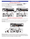
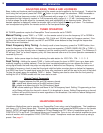
AMPLIFIER CONTROL TRIGGER
If it is desired to use an amplifier control trigger to remotely control an external amp, then the +12VDC and
GROUND should be terminated into an 1/8” (3.5mm) mono mini jack. Plug the mini jack into the amplifier
Control IN that is going to be controlled. If a keypad is also connected to the Reference 5 S2, the amplifier
control trigger can be connected in parallel with the control trigger. See diagram below.
8
ACCESSORIES
V1V2TV
S
OURCEINPUTS
DVD
CD
I
NPUT
OUTPUT
TAPE
P
REAMPOUTPUTS
F
ULL
R
ANGE
HIGH
PASS
SUB
M
ONO
L
+R
Audio/Video Systems Hand-Made in the U.S.A.
BK
&
SB
I
MPLY ETTER!
R
ISKOFELECTRICSHOCK
DONOTOPEN
C
AUTION
ANTENNA
A
M
F
M
VOLTAGE
RS-232
IR
OUTPUT
BALANCEDOUTPUT
F
ULLRANGE
LEFT RIGHT
SERIAL#
G
R
O
U
N
D
R
S
2
3
2
T
R
A
N
S
M
I
T
I
R
D
A
T
A
I
N
P
U
T
C
O
N
T
R
O
L
O
U
T
+
1
2
V
A
CLINE
200 mA Max
C
urrent @ 12V
UsingaEIA-T568BCat-5Cable
RJ-45terminationononeend
andbarewireontheother
CK1.2KeypadConnection
PlugthemaleRJ-45connectorintothe
portontheCK1.2Keypad. Additional
keypadsinazonecanberunoutoftheSlave[OUT].
Master
[IN]RJ-45
Reference5S2Connection
Insertandtightenthewiresintothe
ControlI/OPortfivepinphoenixconnector.
G
R
R
S
2
I
R
FirstColorisPrimaryColor(Secondary)
IROUTPUT - SolidOrange
GROUND-Green/White Stripe&(SolidGreen)
RS232XMIT -White/Blue Stripe
+12V-Orange/WhiteStripe&(SolidBrown)
12VControl-White/Brown Stripe
SolidBlue=N/C
Note: If an IR sensor is
going to be used, only
+12VDC, GND and IR DATA
need to be connected
P/N - 21419
F
U
S
E
F
U
S
E
F
U
S
E
F
U
S
E
F
U
S
E
F
U
S
E
F
U
S
E
F
U
S
E
F
U
S
E
F
U
S
E
F
U
S
E
F
U
S
E
FUSE
CAUTION:FORCONTINUED
PROTECTIONAGAINSTRISK
OFFIREREPLACE ONLYWITH
SAMETYPEAND RATING.
CHANNEL2OUTPUTCHANNEL1OUTPUT
CHANNEL1INPUT CHANNEL2INPUT
CTRL
OUT
12VDC
200mA
CONTROLINALL
OW
SAMPLIFIER
OPERA
TIONW
HENA5-24VSIGNAL
ISAPPLIEDW
ITHA3.5mmMINIJACK
XLR(BALANCED)
RCA(UNBALANCED)
XLR(BALANCED)
RCA(UNBALANCED)
RCAINPUT
XLRINPUT
RCAINPUT
BK
&
SB
IMPLY ETTER!
SERIAL#
CTRL
IN
CA UTI ON
RISKOFELECTRICSHOCK
DONOTOPEN
RI SKOF E LE CT RI CS HO C K
DO
NO TO PE N
ACLINE
POSITIVE
NEGATIVE
POSITIVE
NEGATIVE
CONTROLI/O
www.bkcomp.com
High Performance
Audio/Video Systems
Hand-Made in theU.S.A.
+
1
2
VLOWP OW
E
R
R
I
N
G
TI
P
GRO UN D
SL EEV
E
+
1
2
VC
T
RLE
NA
BL
E
XLRINPUT
Reference200.2S2
V1V2TV
SOURCEINPUTS
DVD
CD
INPUT
OUTPUT
TAPE
PREAMPOUTPUTS
FULL
RANGE
HIGH
PASS
SUB
MONO
L+R
Audio/Video Systems Hand-Made in the U.S.A.
BK
&
B K
&
SB
IMPLY ETTER!
R
ISKOFELECTRICSHOCK
D
ONOTOPEN
R
IS KO
F
E
LE CTR I C
S
HO CK
D
O
N
OT
O
PE N
CAUTIONCA UT ION
ANTENNA
AM
FM
VOLTAGE
RS-232
IR
OUTPUT
BALANCEDOUTPUT
FULLRANGE
LEFT RIGHT
SERIAL#
G
R
O
U
N
D
R
S
2
3
2
T
R
A
N
S
M
I
T
I
R
D
A
T
A
I
N
P
U
T
C
O
N
T
R
O
L
O
U
T
+
1
2
V
ACLINE
200 mA Max
Current @ 12V
200mA Ma x
Cur ren t @12V
Reference5S2
L
L
UNIT OPERATION