


AUDIO / VIDEO CONNECTIONS
Connecting your analog sources to your A/V System Controller
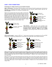
Audio / Video source -
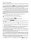
connecting a DVD/VLD player to the A/V System Controller’s analog inputs. Use the same
instructions for connecting to other audio / video sources such as a television, satellite receiver, cable box, etc.
(Omit the video connections for an audio-only component such
as a CD player)
Attach one end of the audio interconnect cable to the left audio
output on the DVD/VLD player, then attach the other end to the
left (white) DVD/VLD audio input on the A/V System Controller.
Repeat for the right (red) audio connection. Attach one end of
the composite video interconnect cable to the video out on the
DVD/VLD player, then attach the other end to the yellow video
input on the A/V System Controller labeled DVD/VLD. Repeat
for the S-video connections if you are using S-video.
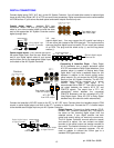
Video Monitor -
Attach one end of the composite video
interconnect cable to the video input on the monitor, then attach
the other end to the yellow video output on the A/V System
Controller’s ZONE OUTPUTS. Repeat for the S-video
connections if you are using S-video. Use Z1 for zone 1 and Z2
for zone 2.
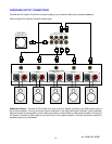
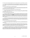
VCR or audio recorder -
connect a VCR to V1 .
Use the same instructions for connecting to the V2 and TAPE
analog inputs. If connecting a cassette deck or other audio-only recorder then omit the video connections.
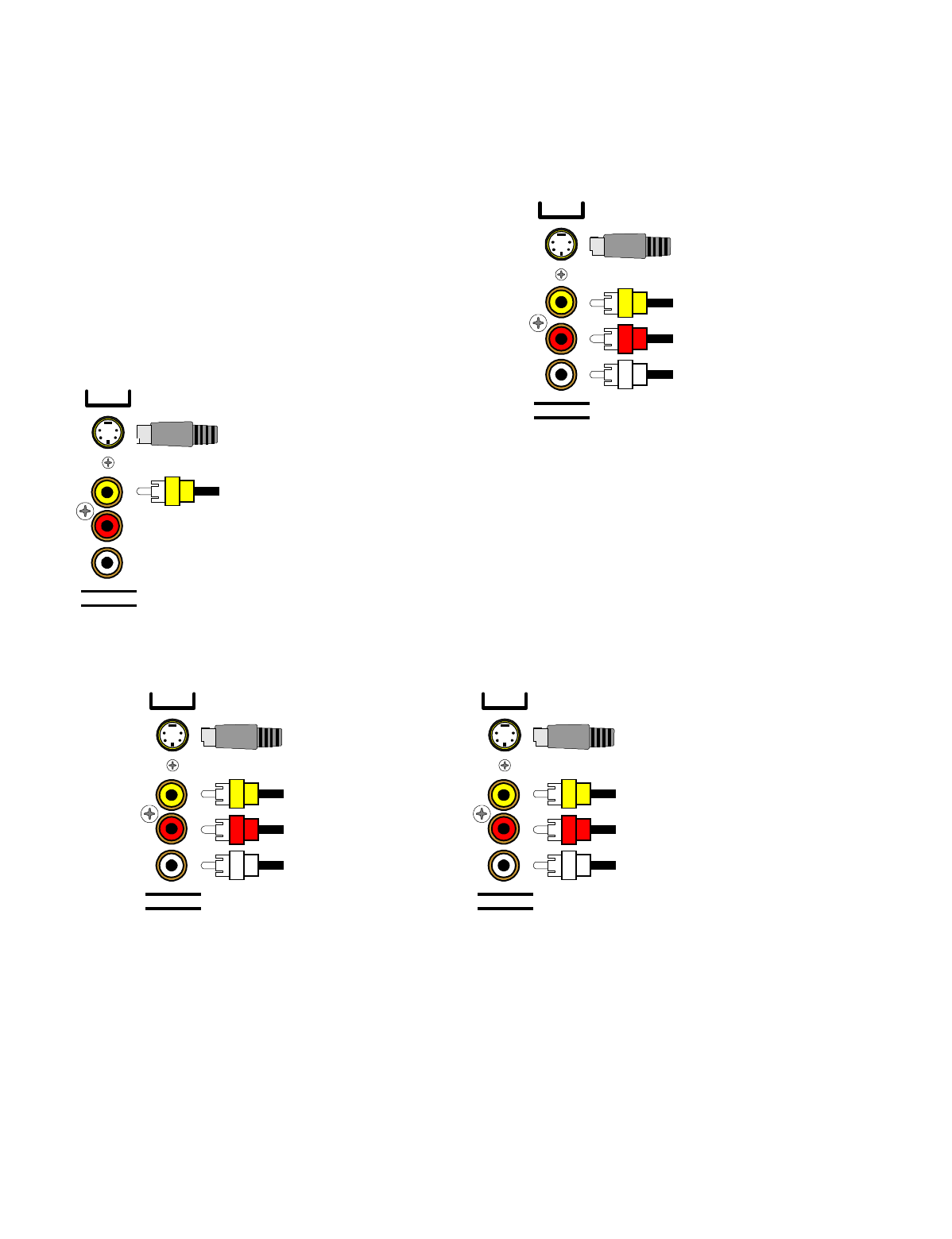
LINE INPUTS
Right audio input
from VCR output
Composite video input
from VCR output
S-Video input
from VCR output
V1
Left audio input
from VCR output
LINE OUTPUTS
Right audio output
to VCR input
Composite video output
to VCR input
S-Video output
to VCR input
V1
Left audio output
to VCR input
Attach one end of the audio interconnect cable to the left audio output on the VCR, then attach the other end to the
left (white) V1 audio input on the A/V System Controller. Repeat for the right (red) audio connection. Attach one
end of the composite video interconnect cable to the composite video output on the VCR, then attach the other
end to the yellow video input on the A/V System Controller labeled V1. Repeat for the S-video connections if you
are using S-video.
Attach one end of the audio interconnect cable to the left audio input on the VCR, then attach the other end to the
left (white) V1 audio output on the A/V System Controller. Repeat for the right (red) audio connection. Attach one
end of the composite video interconnect cable to the composite video input on the VCR, then attach the other end
to the yellow video output on the A/V System Controller labeled V1. Repeat for the S-video connections if you are
using S-video.
11
p/n 12698 Rev. 9808B
LINE INPUTS
Right audio input from
DVD output
Composite video input
from DVD output
S-Video input
from DVD output
DVD
Left audio input from
DVD output
ZONE OUTPUTS
Composite video output
to monitor input
S-Video output
to monitor input
Z1