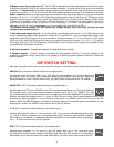
5
CHANNEL CONTROL & MUTING
Each pair of amplifier channels has its own 1/8” mini control input / output (pass through) jack to provide remote
switching of the amplifier audio mute on/off feature. The control input circuit is designed to work as Tip Pos. (+)
and Ring Neg. (-). A minimum of 5VDC @ 1 mA is recommended, and is compatible with up to 24V AC or DC. A
preamplifier’s control output, such as is provided with B&K series preamplifiers, can be utilized to provide a
control signal to the AV1260. When ‘Local’ channel control muting is desired, the proper DIP switch configuration
must be set.
MASTER CONTROL & MUTING
The AV1260 is designed to provide independent control for two groups of amplifier channels, Group A has control
over amplifier channels 1-6, while Group B has control over amplifier channels 7-12. Master control A allows for
single switching of the amplifier audio mute on/off feature on any pair of amplifier channels (1-2, 3-4 or 5-6) with
it’s DIP switch setting configured for Amp off and Sense off. Similarly, Master control B allows for single
switching of the amplifier audio mute on/off feature on any pair of amplifier channels (7-8, 9-10 or 11-12) with it’s
DIP switch setting configured for Amp off and Sense off. The Master control output is a pass through of the
Master control input. Master control out A could be sent to Master control input B to allow any combination of the
12 amplifier channels muting to be controlled via a single source. The control input circuit is designed to work as
Tip Pos. (+) and Ring Neg. (-). A control source capable of sourcing a minimum of 5 VDC @ 1 mA is
recommended, and is compatible with up to 24V AC or DC. (The Master control outputs DO NOT source any
voltage directly, they only PASS through the input voltage at their receptive inputs).
Note: When an 1/8" mini plug is inserted into the ‘Local’ amplifier pairs CTRL IN jack, the Master Control signal is
automatically disabled for that amplifier pair.
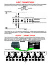
If more than one AV1260 or other units are to be controlled, the control signal can be expanded to include each
successive unit by simply running a 1/8" mini cable from the CTRL OUT connector of the first amplifier to the
CTRL IN connector of the next unit (commonly referred to as ‘daisy chaining’).
*Note: A control voltage is for muting control only. Each amplifier must be connected to its own source of AC
power in order for it to operate.
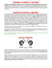
LEVEL CONTROL
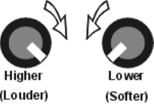
Figure 2
Each pair of amplifier channels have their own ‘Local’ level control. It may be used to equally attenuate the level
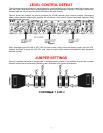
for both amplifiers pairs. The level controls may be reconfigured so that they are bypassed (recommended for
high current output paralleling applications) by moving the jumpers inside the unit. See AV1260's internal
volume selection.
Default from the factory, the level controls are set to full clockwise (no attenuation). Note, there is a single level
control for each pair of amplifiers (1-2, 3-4, 5-6, 7-8, 9-10, and 11-12) therefore, care should be taken in the
assignment of the audio signal source when used in applications when there is no relationship between the two
amplifier pairs (i.e.. separate source material, one from a DVD player the other from a VCR.) Another example
might be when using 4 ohm and 8 ohm speakers together, the 4 ohm (CH 1) speaker may sound louder then the
8 ohm (CH 2) speaker when set to the same level.


