


7
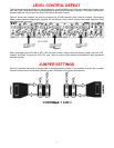
LEVEL CONTROL DEFEAT
The following procedures should only be performed by a qualified technician. Each pair of amplifier channels have
their own ‘Local’ level control that may be bypassed to allow paralleling output channels. The jumper modules are
located inside the unit, on the circuit board, just behind the level controls.
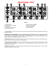
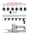
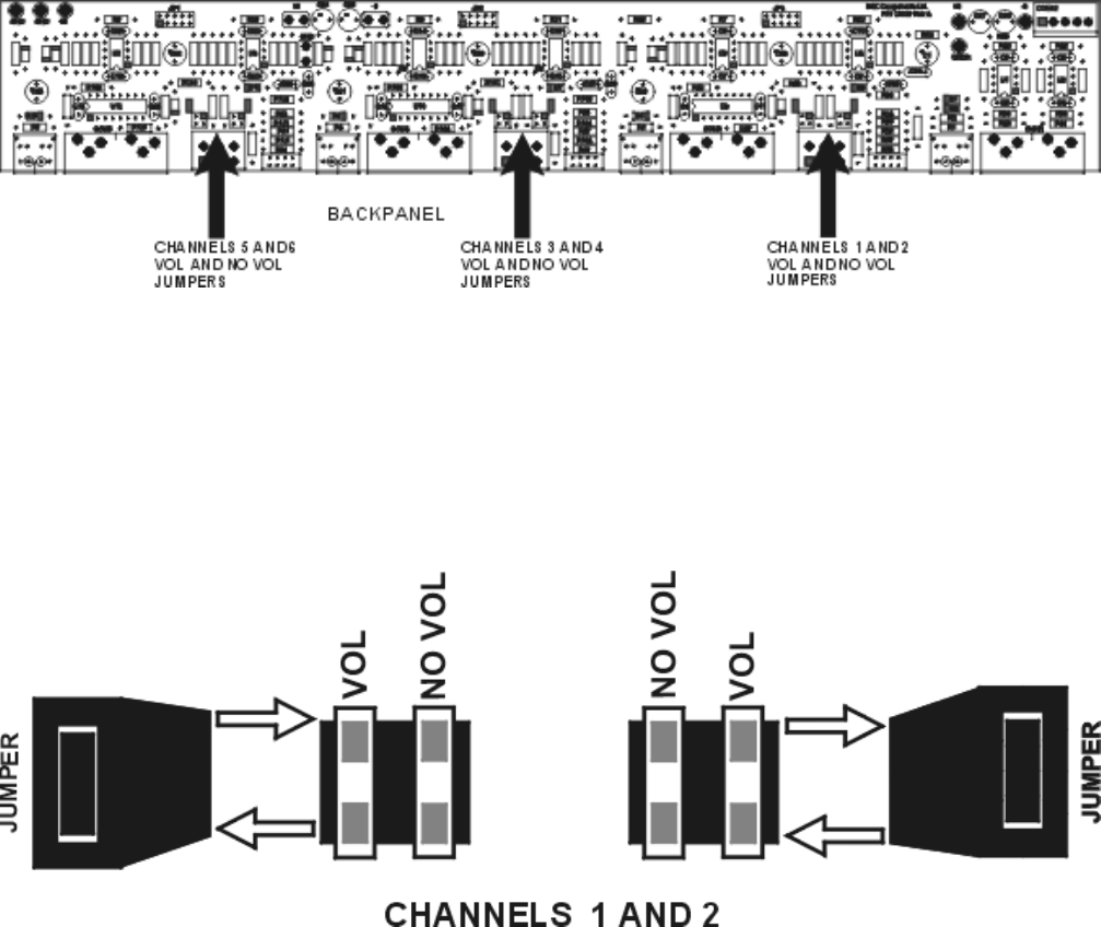
Figure 6 shows how jumpers are used to configure the AV1260 amplifier (level controls enabled). Rearranging
these jumpers allows configuring the amplifier for use without a level control (required for proper operation using
paralleled output channels).
Figure 6
When reconfiguring the AV1260 to NOT USE the level control, simply move the desired jumper from the ‘VOL’
(default) and place it across the ‘NO VOL’ pins. Note, the level control should be disabled for each paralleled
amplifier channel.
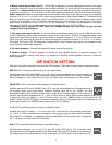
JUMPER SETTINGS
Figure 6 illustrates the jumper modules used in configuring each channel. Each amplifier channel has a jumper
terminal location that is conveniently labeled for easy verification of its current configuration.
Figure 7