


3
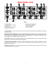
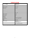
REAR PANEL VIEW
Figure 1
1. AC fuse holder 6. Master control input/output
2. Channel control input/output 7. Bus inputs and outputs
3. Dip switches 8. AC input receptacle
4. Channel inputs and outputs 9. Speaker outputs
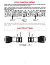
5. Channel level control
1. AC fuse holder - The AC Line fuse. The fuse is an 8 Amp / 250 Volt Slow Blow fuse. Replace with same type
and value fuse only.
2. Channel control input/output - Each pair of amplifier channels has its own 1/8” mini control input / output
(pass through) ‘Local’ control jack to provide remote switching of the amplifier audio mute on/off feature. The
control input circuit is designed to work as Tip Pos. (+) and Ring Neg. (-). A minimum of 5VDC @ 1 mA is
recommended, and is compatible with up to 24V AC or DC.
3. Dip switches - Each pair of amplifier channels has its own DIP switches that are used to configure the audio
signal (‘Local’ or ‘BUS’, mono or stereo and muting control).
4. Channel inputs and outputs - Each pair of amplifier channels has its own ‘Local’ set of audio input / output
(pass through) RCA connections. Typically used for connecting signal patch cables (interconnects) from the
preamplifier to the amplifier.
5. Channel level control - Each pair of amplifier channels has its own DUAL input level control. The level of both
amplifier channels is set via this control.