


4
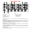
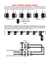
6. Master control input/output (A or B) - The AV1260 is designed to provide independent control for two groups
of amplifier channels, Group A has control over amplifier channels 1-6, while Group B has control over amplifier
channels 7-12. Master control A allows for single switching of the amplifier audio mute on/off feature on any pair
of amplifier channels (1-2, 3-4 or 5-6) with it’s DIP switch setting configured for Amp off and Sense off. Similarly,
Master control B allows for single switching of the amplifier audio mute on/off feature on any pair of amplifier
channels (7-8, 9-10 or 11-12) with it’s DIP switch setting configured for Amp off and Sense off. The Master control
output is a pass through of the Master control input. Master control out A could be sent to Master control input B
to allow any combination of the 12 amplifier channels muting to be controlled via a single source. The control
input circuit is designed to work as Tip Pos. (+) and Ring Neg. (-). A control source capable of sourcing a
minimum of 5 VDC @ 1 mA is recommended, and is compatible with up to 24V AC or DC.
(The Master control outputs DO NOT source any voltage directly, they only PASS through the input
voltage at their receptive inputs).
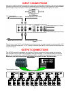
7. Bus inputs and outputs (A or B) - In a similar fashion to the Master control inputs, the AV1260 has provisions
for two independent stereo audio distribution busses, BUS A and BUS B. These are independent stereo audio
inputs which allow BUS A (group A) to source audio to amplifier channels (1-2, 3-4 or 5-6) with it’s DIP switch
‘BUS’ set to ON, while BUS B (group B) is used to source audio to amplifier channels (7-8, 9-10 or 11-12) with it’s
DIP switch ‘BUS’ set to ON. Simultaneously, buffered BUS A and B stereo audio outputs are provided to allow
audio distribution and system expansion.
8. AC Input receptacle - Connect the supplied AC power cord to the amplifier.
9. Speaker outputs - ‘Phoenix’ speaker connectors for easy speaker hook-up. To prevent damage to the
speakers or amplifier, always verify there is no possibility of shorting multiple speaker terminals or loose wire
strands together.
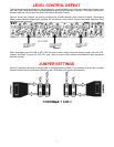
DIP SWITCH SETTING
Each pair of amplifiers have their own set of four DIP switches. The function of each switch is described below:
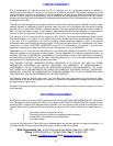
AMP ON: (ON is the factory default setting for all amplifier pairs)
Amplifier pairs with DIP switch ‘AMP’ set to ‘ON’, have the remote Master and Channel switching of
the amplifier audio mute on/off feature disabled. When remote amplifier audio muting is desired by
either the Master or ‘Local’ Channel control input, the ‘AMP’ switch must be set to the ‘Off’ position.
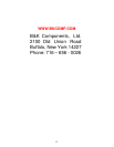
SENSE OFF: (OFF is the factory default setting for all amplifier pairs)
Amplifier pairs with DIP switch ‘SENSE’ set to ‘ON’, have the remote Master and Channel switching of
the amplifier audio mute on/off feature disabled. Amplifier pairs set to use ‘SENSE’ will mute
automatically after a delay of three minutes once no audio signal has been detected. The sense circuit
monitors the amplifiers selected audio, i.e.. ‘Local’ or ‘BUS’ mono or stereo. When remote amplifier audio muting
is desired by either the Master or ‘Local’ Channel control input, the ‘SENSE’ switch must be set to the ‘Off’
position. When the AMP ON feature is desired or automatic muting of the amplifier pairs is not desired, or if the
audio signal is erratic, the ‘SENSE’ switch must be set to the “Off’ position.
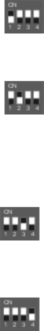
L + R: (OFF is the factory default setting for all amplifier pairs)
Amplifier pairs with DIP switch ‘L + R’ (mono) set to ‘ON’, have the sum of the selected audio inputs,
i.e.. ‘Local’ or ‘BUS’, processed into a composite mono signal source for both amplifier channels.
When mono is not desired, or independent channel amplification of the amplifier pairs is necessary,
the ‘L + R’ switch must be set to the ‘Off’ position
BUS: (OFF is the factory default setting for all amplifier pairs)
Amplifier pairs (channels 1-2, 3-4 and 5-6), with DIP switch ‘BUS’ set to ‘ON’, have their inputs
sourced from the audio signals present at the BUS inputs. When the BUS feature is not desired and
the amplifier pair is to be sourced at the ‘Local’ audio inputs, the ‘BUS’ switch must be set to the ‘Off’.