


9 XENYX 1204USB/X1204USB User Manual
behringer.com
STEREO AUX RETURN MON
The STEREO AUX RETURN MON control has a special function: it can be used to
add an eect to a monitor mix. For example:
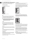
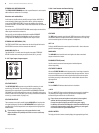
Monitor mix with eect
In this instance, the eects device should be set up as follows: AUX SEND 2 is
connected to the L/Mono input of your eects device, while its outputs are
connected to STEREO AUX RETURN 1. Connect the amplier of your monitor
system to AUX SEND 1. The AUX SEND 1 master control determines the volume of
the monitor mix.
You can now use the STEREO AUX RETURN MON control to adjust the level of the
eects signal routed to the monitor mix.
You can easily use the headphones distribution amplier BEHRINGER
POWERPLAY PRO HA4600/HA4700/HA8000 to provide you with four
(or eight with the HA8000) stereo headphone mixes for your studio.
STEREO AUX RETURN 2 (FX)
The STEREO AUX RETURN 2 control determines the level of signals fed into the
AUX RETURN 2 connectors which are routed to the main mix.
MAIN MIX/ALT 3-4
The MAIN MIX/ALT 3-4 switch routes the signal connected to STEREO AUX
RETURN 2 to either main mix (not pressed) or submix (Alt 3-4, pressed).
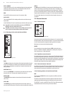
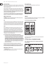
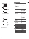
Tape input / tape output2.3.5
Fig. 2.10: 2-track connectors
CD/TAPE INPUT
The CD/TAPE INPUT RCA connectors are provided for connecting a 2 track
machine (e.g. DAT recorder). They can also be used as stereo line input.
Alternatively, the output signal of a second XENYX or BEHRINGER ULTRALINK
PRO MX882 can also be connected. If you connect a hi- amplier with a source
selection switch to the CD/TAPE INPUT, you can easily switch between additional
sources (e.g. cassette recorder, CD player, etc.).
CD/TAPE OUTPUT
These connectors are wired in parallel with the MAIN OUT and carry the main
mix signal (unbalanced). Connect the CD/TAPE OUTPUT to the inputs of your
recording device. The nal output level can be adjusted via the high-precision
MAIN MIX fader.
If you connect a compressor or a noise gate after the 2-track ◊
output, the faders will probably not be able to create a satisfactory
fade-out effect.
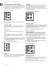
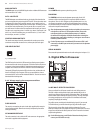
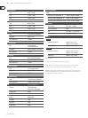
Level meter and monitoring2.3.6
Fig. 2.11: Control room/phones section, level meter
CD/TAPE
The TAPE switch routes the signal from the TAPE IN connectors to the level meter,
the CONTROL ROOM OUT outputs and the PHONES connector this is a simple way
to check recorded signals via monitor speakers or headphones.
ALT 3-4
Similarly, the ALT 3-4 switch routes the signal from the Alt 3-4 bus to the same
path for monitoring purposes.
MAIN MIX
The MAIN MIX switch sends the main mix signal to the above-mentioned
outputs and to the level meter.
PHONES/CTRL R(oom)
Use this control to set control room output level and head-phones
volume respectively.
CD/TAPE TO MAIN
When the CD/TAPE TO MAIN switch is depressed, the 2-track input is routed to
the main mix and thus serves as an additional input for tape machines. You can
also connect MIDI instruments or other signal sources here that do not require
any further processing. At the same time, this switch disables the main mix to
tape output link.
POWER
The blue POWER LED indicates that the device is switched on.
+48 V
The red “+48 V” LED lights up when the phantom power supply is switched on.
The phantom power supply is necessary for condenser microphones and is
activated using the switch on the rear of the device.
Please do not connect microphones to the mixer (or the stagebox/◊
wallbox) while the phantom power supply is switched on.
Connect micro-phones before you switch on the power supply.
In addition, the monitor/PA loudspeakers should be muted before you
activate the phantom power supply. After switching on, wait approx.
one minute to allow for system stabilization.
LEVEL METER
The high-precision level meter accurately displays the appropriate signal level.