


11 XENYX 1204USB/X1204USB User Manual
behringer.com
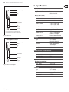
MAIN OUTPUTS
The MAIN outputs carry the MAIN MIX signal and are on balanced XLR connectors
with a nominal level of +4 dBu.
ALT 3-4 OUTPUTS
The ALT 3-4 outputs are unbalanced and carry the signals of the channels that
you have assigned to this group using the MUTE switch. This can be used to route
a subgroup to a further mixing console for example, or or it could be used as a
recording output working in tandem with the main output. This means you could
record to four tracks simultaneously. The icing on the cake, so to speak, is that
you could connect Y-cables to these four outputs and then connect your 8-track
recorder in such a way that you have 2 x 4 tracks (e.g. channel 1 feeds track 1 and
track 2, etc.). In the rst recording pass, you record on tracks 1, 3, 5 and 7 and in
the second pass, on tracks 2, 4, 6 and 8.
CONTROL ROOM OUTPUTS
The control room output is normally connected to the monitor system in the
control room and provides the stereo mix or, when required, the solo signal.
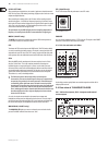
USB INPUT/OUTPUT
Fig. 2.15 USB input/output
The XENYX mixer line has built-in USB connectivity, allowing stereo signals to
be sent to and from the mixer and a computer. The audio sent from the mixer to
a computer is identical to the MAIN MIX. Audio being sent to the mixer from a
computer can be routed to the main mix with the 2-TR/USB TO MAIN button.
Connect the USB type B plug into the USB jack on the mixer, and the other end
into a free USB port on your computer. There are no required drivers, but we
recommend that PC users install the included ASIO driver. The driver can also be
downloaded from behringer.com.
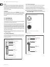
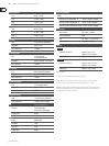
Voltage supply, phantom power and fuse2.4.2
Fig. 2.16: Voltage supply and fuse
FUSE HOLDER
The console is connected to the mains via the cable supplied which meets the
required safety standards. Blown fuses must only be replaced by fuses of the
same type and rating.
IEC MAINS RECEPTACLE
The mains connection is via a cable with IEC mains connector. An appropriate
mains cable is supplied with the equipment.
POWER
Use the POWER switch to power up the mixing console.
PHANTOM
The PHANTOM switch activates the phantom power supply for the XLR
connectors of the mono channels which is required to operate condenser
microphones. The red +48 V LED lights up when phantom power is on. As a
rule, dynamic microphones can still be used with phantom power switched
on, provided that they are wired in a balanced conguration. In case of doubt,
contact the microphone manufacturer!
After the phantom power supply has been switched on, do not connect ◊
microphones to the mixer (or the stagebox/wallbox). Connect the
microphones before you switch phantom power on. In addition,
the monitor/PA loudspeakers should be muted before activating the
phantom power supply. After switching on, wait approx. one minute to
allow the system to stabilize.
Caution! You must never use unbalanced XLR connectors (PIN 1 and 3 ◊
connected) on the MIC input connectors if you want to use the phantom
power supply.
SERIAL NUMBER
Please note the important information on the serial number given in chapter 1.3.3.
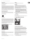
Digital Eects Processor3.
Fig. 3.1: Digital eects module (only X1204USB)
24-BIT MULTI-EFFECTS PROCESSOR
Here you can nd a list of all presets stored in the multi-eects processor.
This built-in eects module produces high-grade standard eects such as
reverb, chorus, anger, delay and various combination eects. The integrated
eects module has the advantage of requiring no wiring. This way, the danger
of creating ground loops or uneven signal levels is eliminated at the outset,
completely simplifying the handling.
These eect presets are designed to be added to dry signals. If you move the
FX TO MAIN control, you mix the channel signal (dry) and the eect signal.
This also goes for mixing eects signals with the monitor mix. The main
dierence is that the mix ratio is adjusted using the FX TO MON control. Of course,
a signal has to be fed into the eects processor via the FX control in the channel
strip for both applications.
On the following page, you will find an illustration showing how to ◊
connect your foot switch correctly.