


7 XENYX 1204USB/X1204USB User Manual
behringer.com
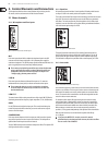
AUX 1 (MON)
In the X1204USB, aux send 1 can be switched pre-fader and is thus particularly
suitable for setting up monitor mixes. In the 1204USB, the rst aux send is
labeled MON and is permanently switched pre-fader.
PRE
When the PRE switch is pressed, aux send 1 is sourced pre-fader.
AUX 2 (FX)
The aux send labeled FX is for sending to eects devices and is thus set up to
be post-fader.
In the X1204USB, the FX send is routed directly to the built-in eects processor.
If you wish to use the internal effects processor, the STEREO AUX ◊
RETURN 2 connectors should not be in use.
X1204USB: you can also connect an external effects processor to aux ◊
send 2, however the internal effects module will be muted.
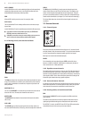
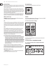
Routing switch, solo and channel fader2.1.4
Fig. 2.4: Panorama and routing controls
PAN
The PAN control determines the position of the channel signal within the stereo
image. This control features a constant-power characteristic, which means the
signal is always maintained at a constant level, irrespective of position in the
stereo panorama.
MUTE/ALT 3-4
You can use the MUTE/ALT 3-4 switch to divert the channel from the main mix
bus to the Alt 3-4 bus. This mutes the channel from the main mix.
MUTE-LED
The MUTE LED indicates that the relevant channel is diverted to the submix
(Alt 3-4 bus).
CLIP-LED
The CLIP LED lights up when the input signal is driven too high. In this case,
turn down the GAIN control and, if necessary, check the setting of the channel EQ.
SOLO
The SOLO switch (X1204USB only) is used to route the channel signal to the
solo bus (Solo In Place) or to the PFL bus (Pre Fader Listen). This enables you to
monitor a channel signal without aecting the main output signal. The signal
you hear is sourced either before (PFL, mono) or after (solo, stereo) both the pan
control and the channel fader (see chapter 2.3.6 “Level meters and monitoring”).
The channel fader determines the level of the channel signal in the main mix
(or submix).
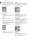
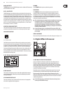
Stereo channels2.2
Channel inputs2.2.1
Fig. 2.5: Stereo channel inputs and LEVEL switch
Each stereo channel has two balanced line level inputs on ¼" connectors for left
and right channels. If only the connector marked “L” is used, the channel operates
in mono. Stereo channels are designed to handle typical line level signals.
Both inputs can also be used with unbalanced jacks.
LEVEL
For level matching, the stereo inputs feature a LEVEL switch which selects
between +4 dBu and -10 dBV. At -10 dBV (home-recording level), the input is
more sensitive than at +4 dBu (studio level).
Equalizer stereo channels2.2.2
The equalizer of the stereo channels is, of course, stereo. The lter characteristics
and crossover frequencies are the same as those of the mono channels. A stereo
equalizer is always preferable to two mono equalizers if frequency correction of a
stereo signal is needed. There is often a discrepancy between the settings of the
left and the right channels when using separate equalizers.
Aux sends stereo channels2.2.3
In principle, the aux sends of the stereo channels function in just the same way as
those of the mono channels. As aux send paths are always mono, the signal on a
stereo channel is rst summed to mono before it reaches the aux bus.
Routing switch, solo and channel fader2.2.4
BAL
The function of the BAL(ANCE) control corresponds to the PAN control in the
mono channels.
The balance control determines the relative proportion between the left and
right input signals before both signals are routed to the main stereo mix bus.
The MUTE/ALT 3-4 switch, the MUTE-LED, the CLIP-LED, the SOLO switch and the
channel fader function in the same way as the mono channels.