


behringer.com
12 XENYX 1204USB/X1204USB User Manual
LEVEL
The LED level meter on the eects module should display a suciently high
level. Take care to ensure that the clip LED only lights up at peak levels. If it is
lit constantly, you are overloading the eects processor and this could cause
unpleasant distortion. The FX control (AUX SEND 2) determines the level that
reaches the eects module.
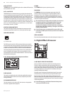
PROGRAM
You can select the eect preset by turning the PROGRAM control. The display
ashes the number of the current preset. To recall the selected preset, press the
button; the ashing stops. You can also recall the selected preset with the
foot switch.
Installation4.
Rack mounting4.1
The packaging of your mixing console contains two 19" rack mount wings which
can be installed on the side panels of the console.
Before you can attach the rack mount wings to the mixing console, you need to
remove the screws holding the left and right side panels. Use these screws to
fasten the two wings onto the console, being careful to note that each wing ts
a specic side. With the rack mount wings installed, you can mount the mixing
console in a commercially available 19" rack. Be sure to allow for proper air ow
around the unit, and do not place the mixing console close to radiators or power
amps, so as to avoid overheating.
Only use the screws holding the mixing console side panels to fasten ◊
the 19" rack mounts.
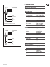
Cable connections4.2
You will need a large number of cables for the various connections to and from
the console. The illustrations below show the wiring of these cables. Be sure to
use only high-grade cables.
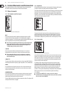
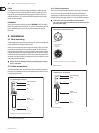
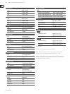
strain relief clamp
sleeve
tip
sleeve
pole 1/ground
tip
pole 2
The footswitch connects both poles momentarily
¼" TS footswitch connector
Fig. 4.1: ¼" TS connector for foot switch
Audio connections4.2.1
Please use commercial RCA cables to wire the 2-track inputs and outputs.
You can, of course, also connect unbalanced devices to the balanced
input/outputs. Use either mono plugs, or ensure that ring and sleeve are
bridged inside the stereo plug (or pins 1 & 3 in the case of XLR connectors).
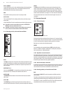
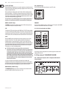
Caution! You must never use unbalanced XLR connectors ◊
(pin 1 and 3 connected) on the MIC inputs if you intend to use the
phantom power supply.
output
For unbalanced use, pin 1 and pin 3 have to be bridged
1 = ground/shield
2 = hot (+ve)
3 = cold (-ve)
input
12
3
1
2
3
Balanced use with XLR connectors
Fig. 4.2: XLR connections
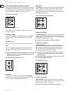
Strain relief clamp
Sleeve
Tip
Sleeve
(ground/shield)
Unbalanced ¼" TS connector
Tip
(signal)
Fig. 4.3: ¼" TS connector