


8
SUPER-X PRO CX3400
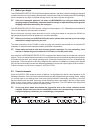
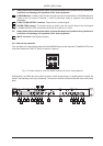
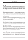
Fig. 2.2: Proper selection of the two MODE buttons for stereo 2-way operation
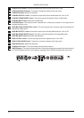
Subsequently, the LEDs above the active controls on the front panel light up, signaling which controls are
active in the operating mode you just selected. The functions of these controls can be seen from the second
strip label. In stereo mode, both channels perform the same functions.
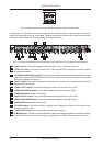
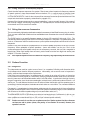
Fig. 2.3: Active control elements on the front panel of the SUPER-X PRO for stereo 2-way operation
1
INPUT control. This control adjusts the input gain from +12 to -12 dB (see control 16).
2
LOW CUT button. This button activates the 25 Hz highpass filter protecting the woofers against
low-frequency signals.
3
LOW/HIGH XOVER FREQ. control. This control governs the crossover frequency between the Low and
High bands. When the XOVER FREQUENCY button on the rear of the unit is pressed, the frequency
range is multiplied by the factor 10.
5
DELAY control. This control delays the Low signal by as much as 2 ms, which is useful to align the
speaker systems in phase.
6
LOW OUTPUT control. Controls the output level of the Low band from +6 to -6 dB.
7
LOW PHASE INVERT button. This button reverses the polarity of the Low output.
8
LOW MUTE button. Mutes the Low band.
12
HIGH OUTPUT control. Controls the output level of the High band from +6 to -6 dB.
13
HIGH PHASE INVERT button. This button reverses the polarity of the High output.
14
HIGH MUTE button. Mutes the High band.
15
CD HORN button. This button provides a special form of frequency correction in the High band for
constant-directivity horns.
30
THRESHOLD control. This control determines the limiter threshold.
31
LIMITER button. This button activates all limiters. Whenever the signal surpasses the limiter threshold,
the LIM-LEDs above the Gain control light up, signaling that the CX3400 cuts back the output level.
2. THE DESIGN CONCEPT