


16
SUPER-X PRO CX3400
Modern systems often use bass reflex cabinets for their woofer or subwoofer systems. Consequently, when
stacking the cabinets, the drivers are usually aligned along the vertical axis of the speaker front, or can at least
be aligned using the available control range of the SUPER-X PRO. Here, runtime correction follows the same
principle as in midrange/high-midrange/tweeter systems. Problems will be encountered only with unconventional
setups (e.g. when the woofers are placed underneath the stage, while the midrange/tweeter systems are flown
above it) or when long woofer horns are used. The latter are the subject of the following discussion.
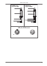
First, measure the horn length. In the case of folded woofer horns this is anything but easy. Use a design
drawing or open the cabinet (usually, a flap or cabinet side wall can be opened easily, for instance, to replace
a defective speaker).
We use a horn length of 1 m as an example. It will make no sense to delay the signal, because the woofer
signal arrives with a 3-ms delay at the mouth of the horn. So, you cannot achieve a correct runtime, unless
you would delay the runtime of the remaining systems in the stack. The pulse response (the main reason for
runtime correction), however, is mainly determined by the mid and tweeter ranges. What you can and should
achieve though is phase coincidence at the crossover frequency. Which is exactly what the
SUPER-X PRO gives you: free adjustability of the crossover frequency.
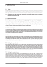
Calculate the frequency whose wavelength corresponds to twice the horn length. At this frequency the output
signal will be reversed by 180° in phase when it comes out from the horn.
The frequency can be calculated as follows:
c
l = f
(see chapter 3.5.2)
Use the known values (speed of sound in m/s; horn length in m) to calculate the frequency:
343 m/s
2 x 1m
= 171,5 1/s = 171,5 Hz
Now, using a crossover frequency of 171.5 Hz and reversing the polarity of the woofer output will result in an
approximate phase correction, which can be fine-adjusted by applying some delay or shifting the crossover
frequency a bit.
General remarks on runtime correction
Only one speaker stack each should be measured and corrected. Begin with the highest crossover frequency
and work your way downward.
+ Once you have completed the runtime correction procedure, please make a note of the relative
positions of the speaker, the adjusted crossover frequencies, delay times, etc. as well as of all
level settings (limiters included). The next time you set up your system, you can start from
these settings and with a bit of luck you will need to make just a few fine adjustments, before
you can turn to the EQs.
+ Never drive different speakers from the same output! The distances which the sound waves
travel before they reach the listener will very likely be different and unavoidably lead to phase
shifts. Additionally, the built-in drivers may have different efficiencies, impedance characteristics
or even reversed polarities.
When the speaker offset is greater than 68.6 cm you can only move the speaker cabinets. Runtime correction
is not the same as the signal delay applied to offset groups of speakers. Here, the entire signal must be
delayed by a much greater amount (a suitable delay circuit is included, for example, in the BEHRINGER
ULTRA-CURVE DSP8024).
3.6 The limiters of the SUPER-X PRO
Limiting the signal in the crossover network is the last resort to protect the system against overloading.
Otherwise, improper handling by the user could lead to serious damage in several drivers.
Each frequency requires its own limiter/compressor control times. The higher the frequency, the shorter the
control times. In the SUPER-X PRO, the control times for the single bands have been determined after long
listening tests, in order to achieve inaudible gain adaptation instead of hard limiting.
3. APPLICATION