


Documentation Number 232D4SS84502 Manual 7
B&B Electronics Mfg Co – 707 Dayton Rd - PO Box 1040 - Ottawa IL 61350 - Ph 815-433-5100 - Fax 815-433-5104
B&B Electronics Ltd – Westlink Comm. Pk – Oranmore, Galway, Ireland – Ph +353 91-792444 – Fax +353 91-792445
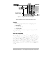
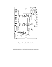
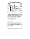
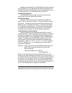
Important: All jumpers must be in the same position, either DCE or
DTE positions. Do not mix positions! Refer to Figure 3 which shows
the Master port configured as a DCE port.
CAUTION: Always power down the Smart Switch before removing
its cover.
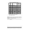
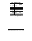
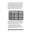
Table 2. DCE MASTER PORT CHART
Pin # Signal Description
Signal
Direction of
DCE Master
Port
2
TD Transmit Data Input
3
RD Receive Data Output
4
RTS Request to Send Input
5
CTS Clear to Send Output
6*
DSR Data Set Ready Output
7
SG Signal Ground <------>
8*
CD Carrier Detect Output
20
DTR Data Term. Ready Input
14**
TD (B) Transmit + Output
15**
TD (A) Transmit - Output
16**
RD (B) Receive + Input
17**
RD (A) Receive - Input
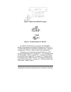
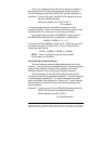
* Pins 6 & 8 are tied together inside the 232D4SS8 and
share the same output. Refer to Figure 5.
** RS-422 Master port option.