


Documentation Number 232D4SS84502 Manual 3
B&B Electronics Mfg Co – 707 Dayton Rd - PO Box 1040 - Ottawa IL 61350 - Ph 815-433-5100 - Fax 815-433-5104
B&B Electronics Ltd – Westlink Comm. Pk – Oranmore, Galway, Ireland – Ph +353 91-792444 – Fax +353 91-792445
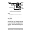
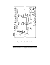
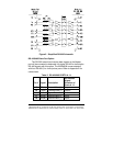
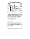
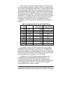
Figure 1. Simplified Functional Diagram
NOTE: This diagram illustrates only the transmit data (TD) signal.
Checklist
The following equipment should be in the shipping carton:
1. Smart Switch
2. Instruction Manual
3. (2) 3 1/2" disks
If any of the items above are damaged or missing contact the
shipper immediately.
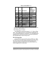
Serial Data Configuration
In order for the host device, which is connected to the Master
Port of the Smart Switch, to select a port, the Smart Switch must be
set to match the host's communication format. This is accomplished
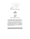
by setting an eight position DIP switch labeled "SW1" located inside
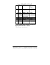
the Smart Switch. Refer to Figure 2. Switch positions 1 through 4
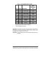
select the baud rate. Switch position 5 selects 7 or 8 data bits.
Refer to Table 1. The remaining switch positions will be discussed
later. Always power down the Smart Switch before changing switch
settings.
Port Combiner
Control Lines
Microcontroller
Master Port
TD
UART
Port ETD
Port HTD
CTS
CTS
Port H
Port A
TD
TD
Port G
Port F
Switch
Control
Port BTD
TD
TD
Port D
Port C
Ports "A-H"
TD
Port A