


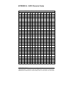

B-2 Appendix B 232D4SS84502 Manual
B&B Electronics Mfg Co – 707 Dayton Rd - PO Box 1040 - Ottawa IL 61350 - Ph 815-433-5100 - Fax 815-433-5104
B&B Electronics Ltd – Westlink Comm. Pk – Oranmore, Galway, Ireland – Ph +353 91-792444 – Fax +353 91-792445
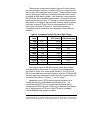
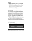
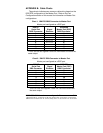
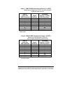
Chart 3. Modem DB25 Connector to Master Port
Master port configured as a DTE port.
Async Modem
Serial Port
DB25 Connector
Signal
Direction
232D4SS8
Master Port (DTE)
DB25 Connector
2 <----------- 2
3 -----------> 3
4 <----------- 4
5 -----------> 5
7 <---------> 7
8 -----------> 8*
20 <----------- 20
* Pins 6 & 8 are tied together inside the 232D4SS8 and share the
same input.
NOTE: When using chart 3 above and connecting a DTE device
to ports A - H of the smart switch, refer to Charts 7 and 8.
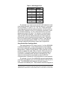
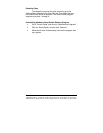
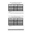
Chart 4. DCE Device w/DB25 Connector to Ports A - H (DTE)
Master port configured as a DCE port.
DCE Device
Serial Port
DB25 Connector
Signal
Direction
232D4SS8
Ports A - H (DTE)
DB25 Connector
2 <----------- 2
3 -----------> 3
4 <----------- 4
5 ----------> 5
6 ----------> 6*
7 <---------> 7
8 -----------> 8*
20 <----------- 20
* Pins 6 & 8 are tied together inside the 232D4SS8 and share the
same input.