


3
Trace round the outer edge of the template
and cut neatly just inside the line.
To improve the mechanical integrity of the
wall and reduce the likelihood of rattles, we
recommend you apply a bead of wood glue
or mastic along the joints between the back
of the plasterboard and the studs in the
vicinity if the speaker.
Run the cable to the aperture, allowing
enough length to comfortably connect the
speaker, but not too much, as the excess
may rattle against the structure.
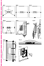
New drywall construction
The speaker can be installed once the wall
is completed in the same manner as
retrofitting, but it is easier to position and
cut the hole if the optional pre-mount kit is
used before the plasterboard (sheetrock) is
fitted.
Staple or nail the PMK to the studs as
described in the instructions with the kit.
Run the cable and secure it to the fixing
point on the PMK. Allow enough length to
comfortably connect the speaker, but not
too much, as the excess may rattle against
the structure.
Results are affected by how well the
plasterboard is attached to the studs and
we recommend gluing as well as screwing
or nailing the panels to the studs in the
vicinity of the speaker.
Once the board is fitted, the inner flange of
the PMK serves as a guide for a hole router
or saw.
If extra acoustic isolation to adjoining
rooms is required or some protection
against the spread of fire, use the optional
back box in place of the PMK. Follow the
instructions with the back box for fitting
and running the cable.
When fitting the plasterboard, use mastic
between the sheets and the back box to
avoid rattles. Rout or saw out the speaker
aperture using the backbox flange as a
guide. Depending on the diameter of the
router, you may need to square off the
corners with a saw.
Solid wall construction
In order for the bass performance not to be
compromised, the speaker requires a cavity
volume of at least 20 litres (0.7 cu ft). This
means that, in a standard 10cm (4 in) thick
wall, the cavity will extend beyond the
boundaries of the speaker frame. It is
possible to provide this cavity simply by using
a lintel, covering the hole with plasterboard
and fitting the speaker as described above for
retrofitting into a drywall. (figure 5) However,
the back box provides a useful means of
defining the minimum volume required.
Follow the instructions with the back box for
fitting and running the cable. If using a wet
plaster finishing method, first paint a layer of
PVA adhesive onto the back box before
plastering to avoid rattles as a result of the
plaster shrinking away from the back box as
it dries.
If using plasterboard, stick the sheets to the
surfaces of the back box using flexible
mastic. Rout out the aperture using the
flange as a guide. Depending on the
diameter of the router, you may need to
square off the corners with a saw.
In all cases, we recommend not using
cement or mortar to fix the back box into
the brick or blockwork. rattles are best
avoided by using flexible mastic and
wedges. (figure 6)
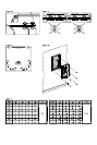
Damping the cavity
Fill the wall cavity or back box, but not the
space immediately behind the speaker, with
unlined fibreglass or mineral wool matting.
The packing density should be just enough
to comfortably prevent the material from
dropping or sagging over time. In an open
wall cavity, fill to a distance of at least
30cm (1 ft) above and below the speaker.
(figure 7)
In the ceiling, drape the matting at the back
of the ceiling board, covering the aperture
and extending at least 30cm (1 ft) around
the speaker into open void. (figure 8)
IMPORTANT: Ensure that the materials you
use meet local fire and safety regulations.
Fitting the speaker
All connections should be made with the
equipment switched off.
With the grille removed, position the wall
frame in the aperture and screw in the
6 screws visible from the front. (figure 9)
These screws automatically swing out
clamping dogs that locate behind the
mounting surface. Ensure that they have
located properly before fully tightening the
screws. A certain amount of flexing of the
frame is allowed to take up unevenness in
the mounting surface, but do not
overtighten the screws as excessive
distortion of the speaker frame may result.
If required, the wall frame and grille mesh
should be painted at this stage, before
fitting the baffle. See also the section
“Customising” below.
Connect the signal cable to the gold plated
spring loaded input terminals on the
crossover and the trigger cable, if used, to
the plastic spring terminals. Ensure the
correct polarity is observed in both cases.
(figure 10)
There are 2 switches on the crossover. One
is marked ‘dipole’ and ‘monopole’. In the
‘dipole’ position, the speaker is in dipole
mode, whatever the status of the 12V
trigger. In the ‘monopole’ position, the
speaker is in monopole mode unless 12V is
applied to the trigger input, when the
speaker becomes dipole.
The second switch is marked ‘A’ and ‘B’.
When viewed from the front, the positive
dipole lobe goes to the right of the speaker
when the switch is at ‘A’ and to the left
when the switch is at ‘B’. (figure 11). Set
the lobes as shown in figure 12, according
to the position of the speaker.
Fit the baffle into the wall frame using the 6
screws provided. (figure 13)
Fit the grille mesh. If the slot width has
become distorted by overtightening the wall
frame clamps, it will be necessary to
remove the baffle, loosen the clamps and
re-tighten them more evenly.
Fine tuning
The choice of monopole or dipole mode
may depend on the type of programme
being played, the speaker’s position in the
installation and, of course, personal
preference.
Multi-channel music often has more
directional cues in the surround sound field
and it may be preferable to have all the
speakers set to monopole. Movie sound is
usually more convincing with a diffuse
sound field and it is usual to set at least the
side speakers to dipole. Rear speakers in
6.1 and 7.1 installations are sometimes set
to monopole, even if the side speakers are
set to dipole, but dipole all round is also an
option. Experiment to find the best settings
for your situation.
The 12V trigger option may be used to
automatically set different modes for
different types of programme. Some
processors can detect whether the
programme being played is music or movie
and assign a trigger accordingly. Some
others can assign a trigger to the input
socket being used and you may wish to
use a different player for music than that
used for movies.
Customising
The frame has a paintable white semi-matte
finish, ready if necessary to be re-finished
to match your own decor. If you do not
wish to remove the speaker baffle, fit the
paint mask before re-finishing. Do not
re-finish the drive units or baffle area
behind the grille. Avoid touching the drive
units, as damage may result.
Before painting the grille, peel off the fabric
scrim from the back, otherwise the pores
will get clogged and the sound will be
impaired. If the scrim does not stay in place
properly when replaced, spray the back of
the grille mesh (NOT the scrim) with a light
coating of 3M SprayMount adhesive or
similar.