


8
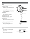
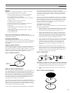
Replacing the Stylus
Replacing the Stylus
The AT-LP120-USB comes supplied with a high-quality Audio-Technica
ATP-2 cartridge. The stylus should be replaced with a genuine
Audio-Technica ATP-N2 stylus.
1. Release the headshell assembly from the tone arm by turning the
locking ring clockwise.
2. Carefully remove the headshell assembly and turn it over so the
stylus is visible.
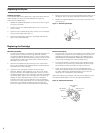
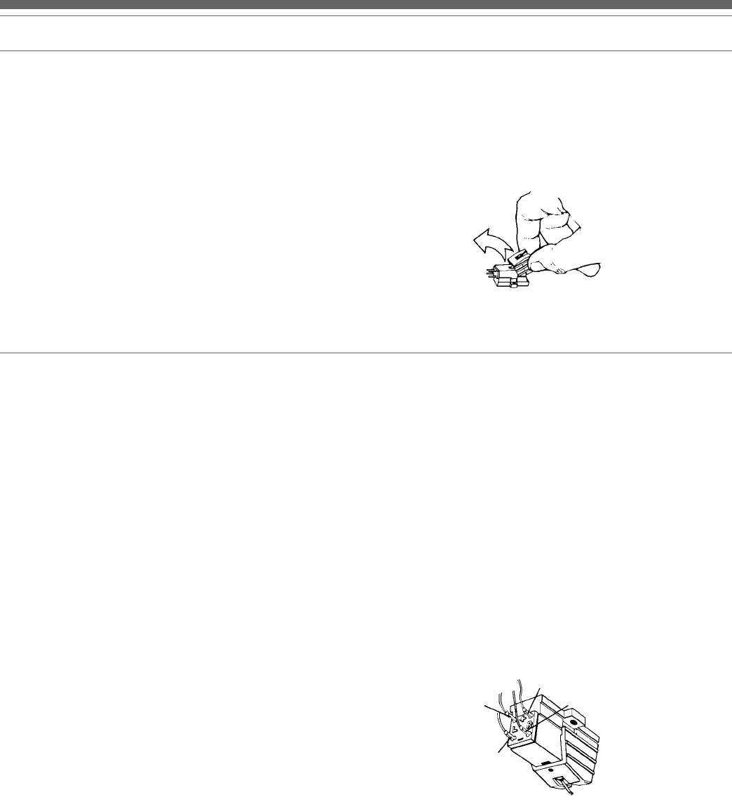
3. Remove the stylus assembly by pulling it away from the cartridge
body at a slight angle. [See Figure 7.]
4. Remove the replacement stylus from its package and carefully
align it with the cartridge body.
5. Gently push the stylus onto the cartridge body, being careful not to
damage the stylus. The stylus assembly should click into place.
6. Replace the headshell assembly on the tone arm and secure with
the locking ring.
Figure 7 – Removing the Stylus
Mechanical Assembly
1. To replace the cartridge, first release the headshell assembly from
the tone arm by turning the locking ring clockwise. Carefully
remove the headshell assembly and turn it over so that the stylus
is visible. Remove the stylus assembly by pulling it away from the
cartridge body at a slight angle. [See Figure 7.] Place the stylus
assembly out of harm’s way.
2. Remove the cartridge body by loosening the two small screws
securing the cartridge to the headshell. Set the hardware aside to
be reused with the new cartridge.
3. Unpack the new cartridge and carefully remove its stylus
assembly. Place the stylus assembly out of harm’s way. Mount
the new cartridge to the headshell assembly. Use the mounting
hardware supplied with the new cartridge or the existing hardware
removed at step 2. Tighten the mounting screws until just snug.
Replace the stylus assembly briefly to check for mechanical
interference with the mounting hardware. The stylus assembly
should click into place. Make certain the new cartridge is properly
positioned in the headcase assembly per the manufacturer’s
instructions. Again remove the stylus assembly for safekeeping.
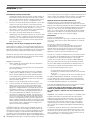
Electrical Connections
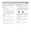
1. Four terminals at the rear of the cartridge are color coded to match
standard wiring in stereo tone arms. [See Figure 8.] Connect the
cartridge with the slip-on lugs provided on the headshell wiring.
NEVER SOLDER TO CARTRIDGE TERMINALS! Heat applied to
the terminals will damage the internal cartridge wiring.
2. For monaural operation, the left and right signal leads should be
connected to the monaural output terminal and the left and right
ground leads should be connected to the ground terminal.
3. Finally, gently push the stylus onto the cartridge body being
careful not to damage the stylus. The stylus assembly should click
into place. Replace the headshell assembly onto the tone arm
taking care not to damage the stylus assembly.
(Note: After replacing the cartridge, reset the tone arm balance, stylus
force and anti-skate based on the new cartridge’s specifications.)
Figure 8 – Electrical Connections
Left Output
(White)
Right Output
(Red)
Right Ground
(Green)
Left Ground
(Blue)
Replacing the Cartridge