


English
5
Initial Setup
Unpacking
Carefully unpack the turntable and verify that the following parts are
included and intact:
• Slip mat (above the dust cover)
• Dust cover (above the turntable)
• Platter (under the turntable)
• Dust cover hinges (accessory section of the
foam packaging)
• 45 RPM adapter (accessory section)
• Counterweight (accessory section)
• Headshell with pre-mounted cartridge
(accessory section)
• Power cord (accessory section)
• USB cable
• Dual RCA (female) to 3.5 mm (1/8") mini-plug (male)
stereo adapter cable
• Dual RCA (female) to 3.5 mm (1/8") mini-plug (female)
stereo adapter cable
• Audacity software (CD)
WE RECOMMEND THAT YOU SAVE ALL PACKAGING
MATERIALS FOR POSSIBLE FUTURE STORAGE, MOVING OR
SHIPPING.
Assembling the Turntable
The AT-LP120-USB requires some assembly before first use.
IMPORTANT: Do not connect the AC power cord until assembly is
complete.
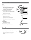
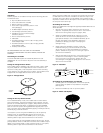
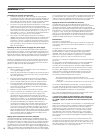
Setting the Voltage Selector Switch
This turntable has the capability to be used with either 115V or 230V
AC power, 60/50 Hz. The voltage selector switch is located on the
top of the housing deck, under the platter. Set the switch according
to the voltage in your area. [See Figure 4.] (Note: The turntable comes
shipped with the voltage selector switch set for 115V AC.)
Figure 4 – Voltage Switch
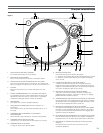
Setting the Pre-amp Selector Switch
For increased flexibility of use, this turntable has an internal stereo
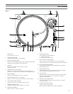
phono pre-amplifier. The pre-amp selector switch located in the rear-
panel of the turntable [See Figure 3, page 4, #29], selects the internal
stereo pre-amplifier (LINE OUT), or bypasses the pre-amp (PHONO
OUT) for use with systems having specialized magnetic phono input
jacks. The audio output cable’s Red RCA-type plug is the Right channel;
the White plug is the Left channel.
If the system you are using has a PHONO input, set the pre-amp
selector switch to the PHONO OUT position and connect the
turntable’s output cables to the PHONO inputs on your system,
observing Red for Right channel and White for Left channel.
If your system does not have a PHONO (magnetic phono) input, set the
pre-amp selector switch to LINE OUT and connect the turntable’s output
cables to the Auxiliary (AUX) or other high-level inputs on your system,
observing Red for Right channel and White for Left channel.
When using the turntable with a computer sound card, set the switch
to LINE OUT and connect the turntable to the audio line input on the
computer sound card. Note: An audio adapter (not included) may be
required to interface the two RCA jacks of the turntable output cable to
the computer sound card input.
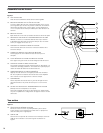
Assembling the Tone Arm
(Note: The headshell and cartridge are supplied pre-assembled with the
AT-LP120-USB.)
1. Remove the vinyl tie used to secure the tone arm during
shipment. Temporarily secure the tone arm in the tone arm
rest with the locking clamp. [Figure 2, page 4, #23.]
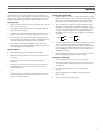
2. Attach the headshell assembly by inserting it into the
socket at the front of the tone arm [See Figure 5.] (It’s
good practice always to hold a headshell assembly by the
left and right edges of the headshell to reduce the
possibility of damaging the stylus or disrupting the
cartridge wiring.)
3. While holding the headshell in position, rotate the
headshell locking ring counter-clockwise (to the left).
As the ring turns, it pulls the headshell into its seated
position. (Rotate the ring a full turn to the right to permit
removal of the headshell.)
4. With its black dial toward the front, use a screwing motion
to attach the counterweight to the arm extending back
from the tone arm pivot [Figure 2, page 4, #27]; the
counterweight will engage the spiral groove in the rear arm
section and move forward.
Figure 5 – Headshell
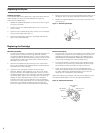
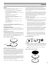
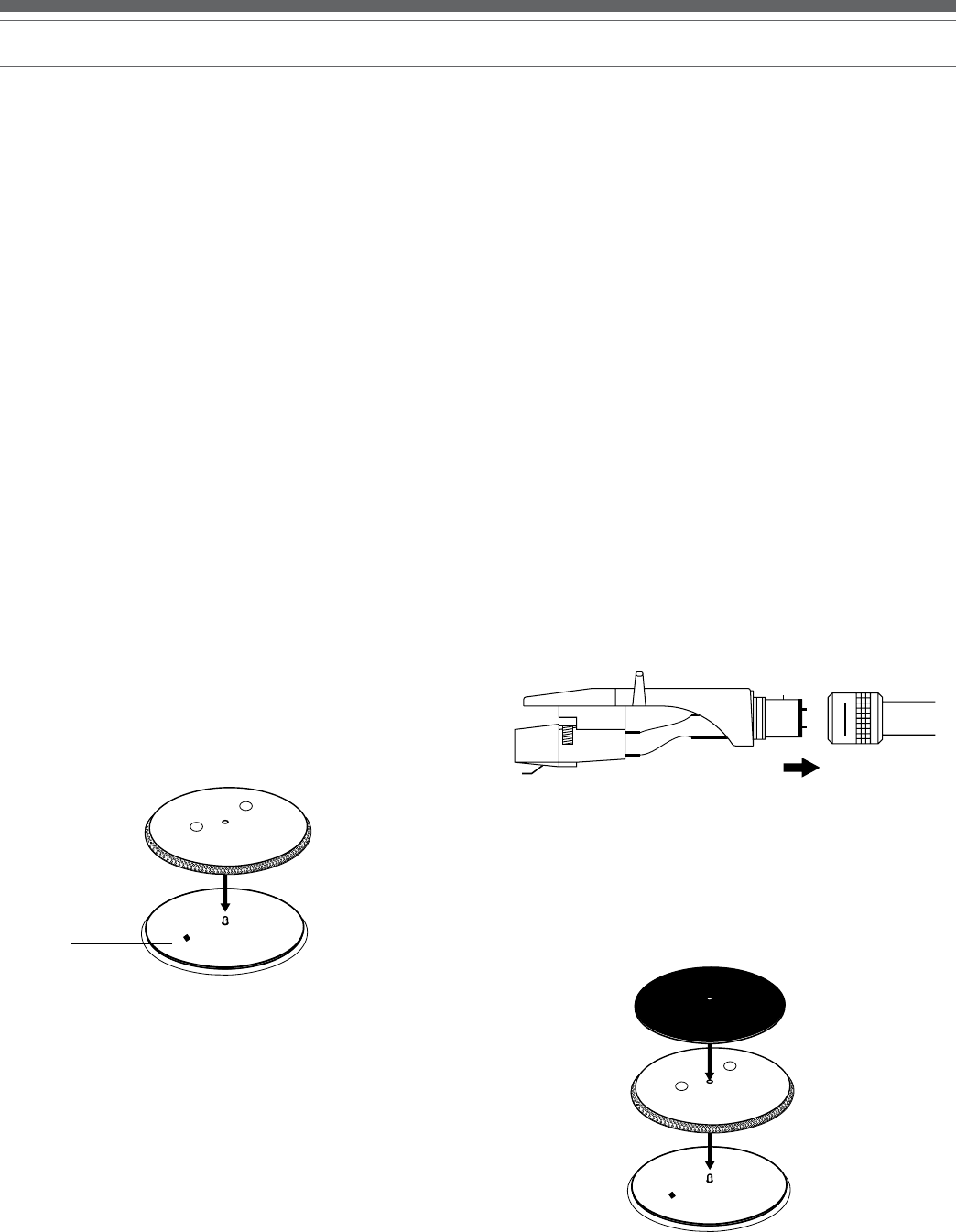
Assembling the Turntable Platter and Slip Mat
1. Carefully place the turntable platter on the center spindle,
making certain the platter is fully seated on the spindle.
[See Figure 6.]
2. Place the soft black slip mat on top of the platter.
Figure 6 – Platter and Slip Mat
Voltage
switch