


ASUS P4GD1ASUS P4GD1
ASUS P4GD1ASUS P4GD1
ASUS P4GD1
2-252-25
2-252-25
2-25
3.3.
3.3.
3.
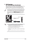
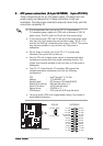
IDE RAID connectorsIDE RAID connectors
IDE RAID connectorsIDE RAID connectors
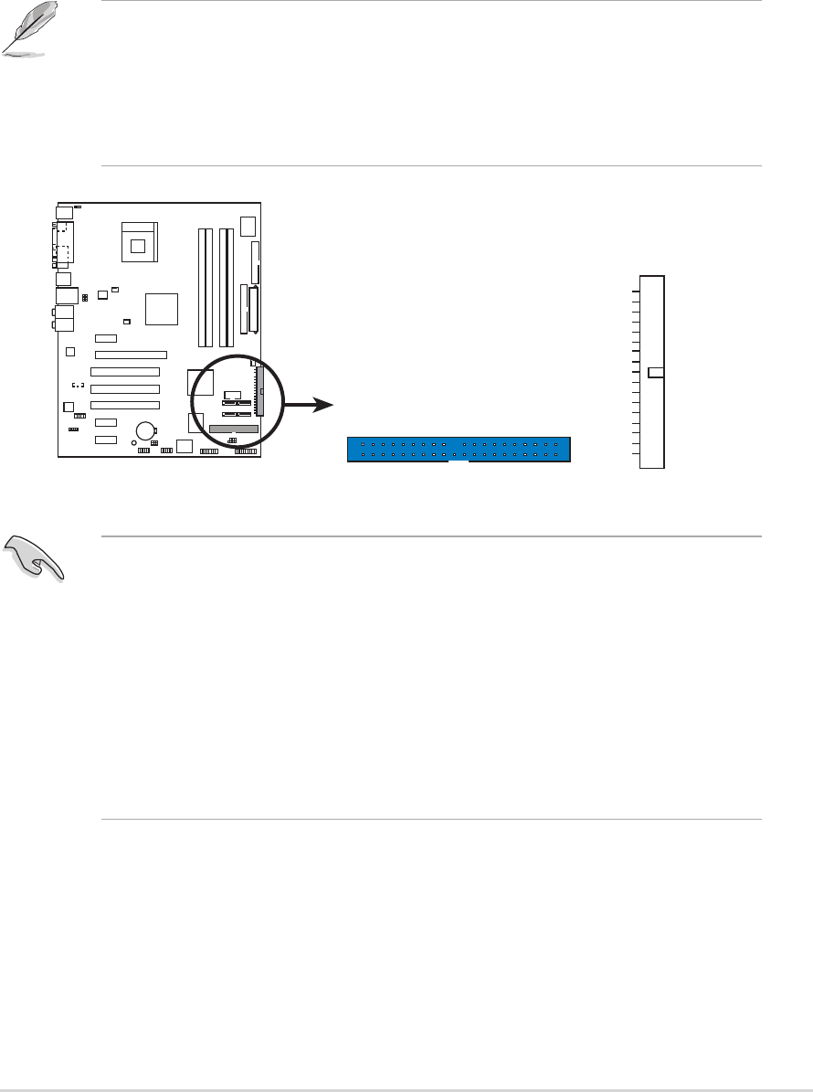
IDE RAID connectors
(40-1 pin PRI_RAID [blue], SEC_RAID [black])(40-1 pin PRI_RAID [blue], SEC_RAID [black])
(40-1 pin PRI_RAID [blue], SEC_RAID [black])(40-1 pin PRI_RAID [blue], SEC_RAID [black])
(40-1 pin PRI_RAID [blue], SEC_RAID [black])
These connectors are for Ultra ATA 133/100/66 signal cables. These
connectors support up to four IDE hard disk drives that can be
configured as a disk array through the onboard IDE RAID controller.
Refer to Chapter 5 for details on how to set up RAID configurations.
• Before creating a RAID set using Ultra ATA hard disks, make
sure that you have connected the Ultra ATA signal cable and
installed Ultra ATA 133/100/66 hard disk drives.
• The system automatically assigns the boot sequence of ATAPI
devices connected to the IDE RAID connectors.
• The ITE
®
8212F controller supports a maximum of 2 Ultra ATA hard
disk drives.
• Set both drives either as Master or Slave before configuring a RAID 1
set.
These connectors are set to IDE mode by default. In IDE mode, you can
connect IDE devices to these connectors such as boot/data hard disk
drives or optical drives. If you intend to create an IDE RAID set using
these connectors, set the
ITE8212F ControllerITE8212F Controller
ITE8212F ControllerITE8212F Controller
ITE8212F Controller item in the BIOS to
RAID Mode. See section “4.4.6 Onboard Devices Configuration” for
details.
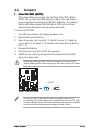
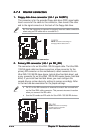
P4GD1
P4GD1 RAID connectors
NOTE: Orient the red markings
(usually zigzag) on the IDE
cable to PIN 1.
PRI_RAID
SEC_RAID