


9
Operating Manual - DPX-200 Parametric Equalizer - Compressor/Limiter
a channel that’s being used for something important and
use it to tailor the sound of this channel exactly the way
you want.
Large Room Equalization
Large rooms tend to suffer from multiple reflec-
tions with long time delays, long reverberation times, and
“ring-modes”, all of which lead to reduced intelligibility
and a generally “muddy” sound. As sound travels long
distances through the air, high frequencies are attenuated
more than low frequencies. In general, large rooms ben-
efit from some low frequency roll-off, high frequency
boost, and attenuation of ring mode frequencies.
8.2 Compressor - Limiter Applications
As the functional name implies, a compressor/
limiter can be divided into two basic categories, limiting
and compressing. When used as a protective device to
prevent audio levels from overloading systems such as
tape recorders, power amplifiers, speakers, or transmit-
ters, it is generally referred to as a limiter.
It may also be used to create special effects and
unusual sounds for recording and musical performance
by deliberately reducing the dynamic range of a signal,
creating a much louder or fuller sounding signal without
increasing the loudness peaks, in which case it is referred
to as a compressor.
The Limiter As A Protective Device
The DPX-200 compressor/limiter section pro-
vides fast and accurate gain control for the prevention of
sound system overload due to unexpected transients.
Sound system distortion is usually the result of amplifi-
ers running out of power, in which case nice round wave-
forms turn into harsh sounding squared-off waveforms.
Looking at it from the perspective of the speaker dia-
phragm, this means that, whereas in normal operation the
diaphragm is required to accelerate, slow down, smoothly
change direction, and accelerate again, distorted opera-
tion requires an instant acceleration, instant stop, a change
of direction, and instant acceleration again.
Since speaker diaphragms are subject to the laws
of physics, they won’t take this kind of punishment for
long. The diaphragm may shatter, or its voice coil may
overheat. In addition to the damaged caused by sustained
overload, the speaker may also be damaged by occasional,
one-shot high level overload, for example, the sound of a
microphone falling face-first onto a hardwood floor. Even
if this type of transient doesn’t destroy a speaker outright,
it may damage the speaker surround in such a way as to
cause mechanical abrasion and future failure.
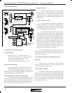
Alternatives For Sound Installations
To install a compressor/limiter in a sound sys-
tem using a passive crossover, insert it between your mix-
ing console output and the power amplifier input. For
systems using electronic crossovers, there are two ways
to use a compressor/limiter. It may be inserted between
the mixer output and the crossover input, in which case it
will act on the entire audio frequency spectrum. Alter-
nately, if the limiter is inserted between an output of the
electric crossover and the input of a power amp, it will
only affect a specific band of frequencies.
Recording
The Ashly limiter can be used to prevent tape
saturation in analog recording. Also, with modern trends
toward inexpensive digital recording, it remains neces-
sary to protect against input overload. With digital re-
cording, the information stored on tape, hard disk, optical
disk, etc., is either a 1 or 0, so actual signal level on the
tape is not the concern it is with analog recordings, in
fact it is not even a user controllable parameter. What is
of concern however, is the signal level applied to the A-D
(analog to digital) converters. If clipping occurs at the
converter input stage, the resulting distortion is most un-
pleasant, and will be recorded digitally as if they were
part of the original audio signal, forever mixed with the
audio. To prevent converter distortion while preserving
the extended dynamic range of digital recording, look up
the max input level of your recorder/converter and set up
the limiter as follows:
1. Set Gain to 0.
2. Set Threshold to 2-3 dB below max converter
input.
3. Set Ratio to 10.
4. Set Attack to 2 mS.
5. Set Release to .2 Sec.
6. Set Output level to 0.
If you are exceeding threshold frequently, your
input signal is probably too high and should be turned
down. Of course, every situation is different, so experi-
mentation before final recording is always a good idea,
but this is a good starting point.
To obtain a gentler limiting action at the expense
of some dynamic range, decrease the threshold to -15 and
the ratio to 3-5. This is also a good starting point for
analog recording.