


7
Operating Manual - DPX-200 Parametric Equalizer - Compressor/Limiter
The input meter takes its signal just after the gain con-
trol, and will indicate input signal level regardless of out-
put levels or limiter settings. The output meter display
takes its signal from the actual output of the unit, so ev-
ery control that affects the output will also have an effect
on output meters. Used in conjunction with the gain re-
duction meters, input/output meters prove to be an ex-
tremely useful diagnostic tool when working with system
dynamics and level control.
7. CONNECTIONS AND CABLES
7.1 Balanced and Unbalanced Audio Connections
Balanced signal connections are preferred in pro
audio applications because of their improved immunity
to induced hum and noise. A properly shielded and wired
balanced input stage on any audio product will reject most
unwanted noise (RFI, EMI) picked up by the cable, as
well as minimize ground loop problems. Therefore it is
always advantageous to use balanced connections when
running signal more than ten or fifteen feet, although par-
ticularly noisy environments may require that even short
patch cables be balanced.
Unbalanced connections are used mostly for short
distance, high level signals (0dBu nominal). Most exter-
nal EMI noise pick-up will be
masked under the noise floor of the
signal, assuming there is little or no
gain following the unbalanced signal.
If a gain stage does follow a signal,
or if externally sourced noise per-
sists, use balanced connectors.
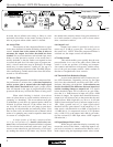
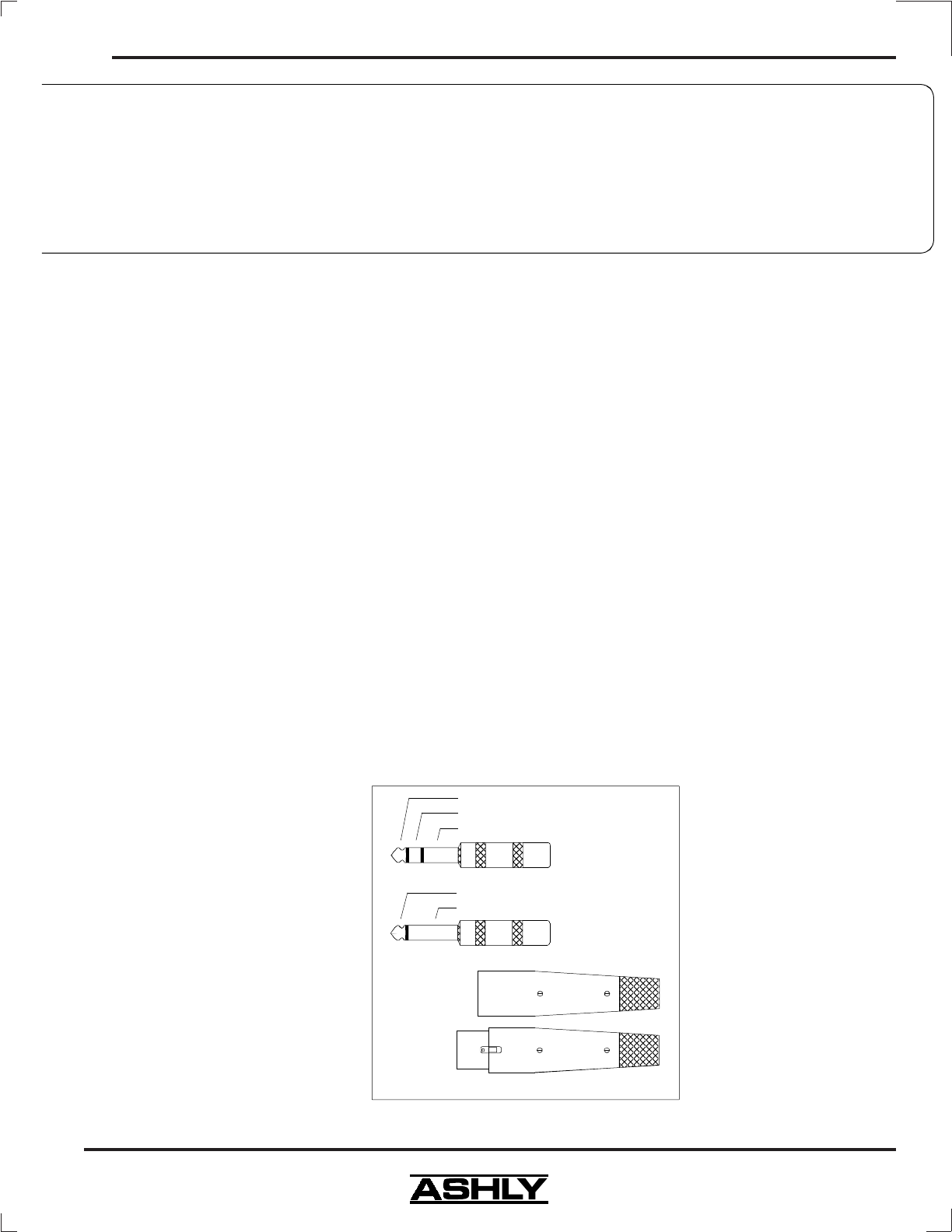
7.2 Inputs and Outputs
The DPX-200 uses two dif-
ferent audio connector types. 1/4"
TRS (tip-ring-sleeve) phone jacks,
and three pin XLR connectors will al-
low interfacing to most professional
audio products. Ashly TRS balanced
connections use the tip as (+) and the
ring as (-) signal, with sleeve used for
ground. Ashly XLR connectors use
pin 2 (+) and pin 3 (-)
with pin 1
ground. Inputs are 20KΩ active balanced using preci-
sion 1% metal film resistors, outputs are 200Ω "pseudo-
balanced", which means they have balanced impedance
with a single-ended signal source, and can be wired bal-
anced or unbalanced. When possible, we recommend
balanced connections between all components in your
system.
If inputs are used unbalanced, the signal should
be on the (+) connection and the (-) connection must be
tied to ground, or signal loss will result. While a mono
phone plug used as an unbalanced connection will auto-
matically ground the (-) ring of the jack, XLR's will not
automatically do this, so attention must be given to proper
wiring.
7.3 Chain Switch
The chain switch on the back panel allows the
output of the parametric equalizer to be fed directly to
the input of the compressor/limiter, with no external cable
required. When the chain switch is in, the input connec-
tors to the compressor/limiter are removed from the cir-
cuit, while the equalizer outputs remain functional.
7.4 Compressor/Limiter Detector Loop - Ducking
The DPX-200 com-
pressor/limiter has a TRS In-
sert DETECTOR PATCH
point which can be used as a
"ducking" input, or in con-
junction with an equalizer to
produce frequency-sensitive
limiting. Various uses of the
detector patch are discussed
under TYPICAL APPLICA-
TIONS.
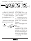
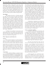
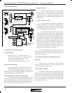
Audio Connector Types
Tip (+)
Ring (-)
Sleeve (Gnd)
Stereo Phone Plug
used for balanced
2 = (+)
3 = (-)
1 = (gnd)
XLR pins are
numbered
on the
connector
insert.
XLR Male
XLR Female
Tip (+)
Sleeve (Gnd)
Mono Phone Plug
used for unbalanced
INPUTS are Active Balanced.
OUTPUTS May Be Wired
Balanced Or Unbalanced.