


5
Operating Manual - DPX-200 Parametric Equalizer - Compressor/Limiter
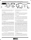
5.5 Parametric Filters
Two 20Hz-20KHz parametric filters allow cus-
tom tailoring of EQ points, most useful for feedback con-
trol, resonance compensation, or other types of frequency
specific voicing. Each parametric filter consists of three
main controls, frequency, bandwidth, and level. Also, an
in/out switch for each filter facilitates easier setups by
allowing comparisons between filtered and unfiltered sig-
nal. A green LED turns on when the filter is engaged.
Frequency: The outer concentric frequency con-
trol determines the filter's peak frequency, or the point
that is boost or cut. A peak filter, as the name implies,
has a symmetrical rise and fall around the center fre-
quency, as opposed to the plateau nature of a shelving
filter. For maximum frequency resolution on the para-
metric filter, a frequency range switch divides the cali-
brated frequency labels by 10, meaning that if the
frequency control is set at 1K, and the range switch is
then pressed in, the frequency is now 100Hz instead of
1KHz. Tick marks on the face panel are calibrated to
ISO 1/3 octave center frequencies.
Bandwidth: The inner concentric bandwidth
control determines how broad or narrow the peak filter
coverage is, and is expressed in octaves. For general tone
control, use a broader bandwidth. For notching out feed-
back frequencies, use a narrower bandwidth. Being able
to optimize bandwidth for the job at hand is the main
reason parametric equalizers are preferred for notching
and feedback control.
Level: As with the shelving filters, the level con-
trol boosts or cuts the frequency by up to 15 dB at the
filter peak.
5.6 EQ Clipping
The equalizer section has its own clip LED in
case both the EQ and comp/limiter are wired indepen-
dently. All critical signal points within the parametric
EQ are monitored for signal level which exceeds +19dBu.
5.7 EQ Master Switch
The EQ master switch allows easy comparison
between filtered and unfiltered signal. A green LED next
to the switch turns on when the four filters are engaged.
Note that the gain control is always active regardless of
the setting of the EQ master switch.
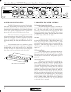
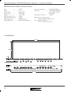
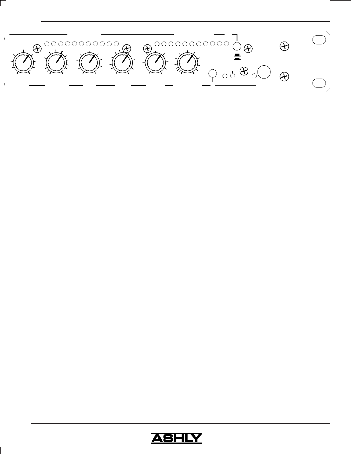
6. COMPRESSOR - LIMITER CONTROLS
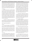
6.1 Gain
The Gain control is used to adjust incoming sig-
nal level to the VCA circuit. It is always active, so
switching out the limiter function has no effect on this
control. Used in conjunction with the input/output level
meter display, this control is useful for setting up optimal
system levels. This control should normally be left at
"0" to achieve accurate threshold calibration.
6.2 Threshold
The threshold control has a range of -40dB to
+22 dB, allowing applications from low level compres-
sion to high level limiting. The threshold control de-
termines the audio level above which gain reduction
occurs. When the threshold LED comes on, that means
that gain reduction is beginning to occur, due to input
signal peaks exceeding the selected threshold in dB.
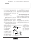
6.3 Ratio
This control determines the resultant change in
output level to changes in input level for all signals above
threshold. The numbers printed around the ratio con-
trol are calibrated in db and indicate the increase in
input (above threshold) required to produce a 1db in-
crease in output. This can be expressed conveniently as
a ratio. If the output remains constant no matter how high
the input level, we have an infinite (∞) input/output ra-
tio. It should be remembered that the ratio control has no
effect on signals which are below threshold.
There is a common but incorrect notion that lim-
iting always implies the use of an infinite ratio. Although
there are times when an infinite ratio is desirable, there
will be situations where infinite, or “hard”, limiting ac-
tion is neither appropriate nor necessary. In fact, it should
dB
∞
+20
+15
+10
+6
+3
0
-3
-6
-10
-20
-
.1
.2
.5
1
2
3
Sec
20
.5
.2 20
1
1.5
2
3
4
5
10
15
mS
2
∞
2.5
3
5
7
10
30
dB
+22-40
+20
+10
+6
+3
0
-3
-6
-10
-20
dB
+15-15
+6
+3
0
-3
-6
-10
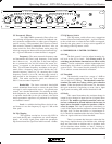
2Th. 4 6 8 10 12 14 16 18 20 -15-18 -12 -9 -6 -3 0 +3 +6 +9 +20
Gain Reduction (dB) Input/Output Level (dB)
Clip
Gain
Threshold Ratio Attack Release Output Level In
Power
Output
Input
+10
Mic
Phantom
Pwr