


6
Operating Manual - DPX-200 Parametric Equalizer - Compressor/Limiter
be noted that an infinite ratio setting is likely to cause
noticeable side effects in the sound, and may not be us-
able on programs where subtle control is desired.
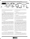
6.4 Attack Time
The response of the compressor/limiter to signal
levels above threshold is further defined by the attack time
control. Attack time is the amount of time it takes to
attenuate the output level after threshold has been
reached. For very fast transients, such as hand claps, snare
drums, or other percussive sounds, a fast attack time is
usually desirable so that the limiter can respond in time
to control the peak level. On other types of program ma-
terial, a slower attack time may be preferred. An abrupt
attack may, on some material, “square off” the top of a
waveform, producing a distorted sound. The DPX-200 pro-
vides continuously variable attack times from 200 micro-
seconds to 20 milliseconds.
6.5 Release Time
Another parameter which affects compressor/lim-
iter performance is release time, or the time required to
restore system gain to normal after the input signal
has fallen below threshold level. Again, proper release
time will depend on the type of program material being
processed and the way in which the limiter is being used.
When subtle limiting is desired, slow release
times are often chosen to avoid condition referred to as
“pumping” or “breathing”. This occurs when overall gain
is modulated up and down by repeated peaks which are
followed by quieter intervals. If the release time is set
too fast, then the overall level will jump up and down,
producing an objectionable and unsettling effect. Note
that, in some cases, an individual track or channel which
seems to be pumping may sound acceptable when heard
in context of a complete mix.
A unique feature of all Ashly compressor/limit-
ers is the incorporation of a double release-time con-
stant. When a conventional compressor/limiter is adjusted
for slow release times, transients such as mic “pops” may
cause a severe reduction in gain followed by a slow fade-
up, making the action of the limiter very obvious. With
the double time constant, release from gain reduction af-
ter a brief transient is always fast, with a slower release
after a sustained overdrive.
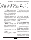
6.6 Output Level
Output level control is provided to fully cut or
restore up to 18 dB of system gain. For unity gain, set
the control to 0. NOTE: When the compressor/limiter is
switched out, the output control still functions.
6.7 In/Out Switch
This switch enables you to quickly hear the com-
pressor/limiter in or out of the audio chain. When the
switch is in the out position, all limiting and compres-
sion controls and functions are bypassed, with the excep-
tion of the gain and output controls, which continue to
function as straightforward level controls.
6.8 Threshold/Gain Reduction Display
As soon as the threshold level is reached, the yel-
low LED illuminates. Depending on how far the input
level rises above threshold, successive red LED’s will il-
luminate, indicating gain reduction. Gain reduction can
best be described as the difference between input level
and the resulting change to output level. For signals
below threshold, there will of course be no gain reduc-
tion, that is, a 10dB increase in input will yield a 10dB
increase in output. For signals above threshold however,
output level will increase only to the extent that the ratio
control allows. With a high ratio, say 20 or so, it will take
20dB of increased input level to increase output level by
1dB. With a gentler ratio of 3:1, input signals above
threshold will be “gain-reduced” at the output by 1/3. In
other words, with threshold set at 0dB, a signal peak at
+12 dBV that is 3:1 compressed (ratio at 3) will produce
only +4 dB (12÷3) at the output, and 8 dB of gain reduc-
tion has occurred (12 dBV input minus 4 dBV output=8
dB reduction.)
6.9 Input/Output Meter Select
While the gain reduction display accurately rep-
resents the action of the limiter, comparing input to out-
put levels in real time is somewhat more intuitive, and is
made simple using the input/output meter select switch.
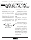
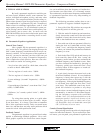
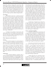
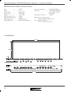
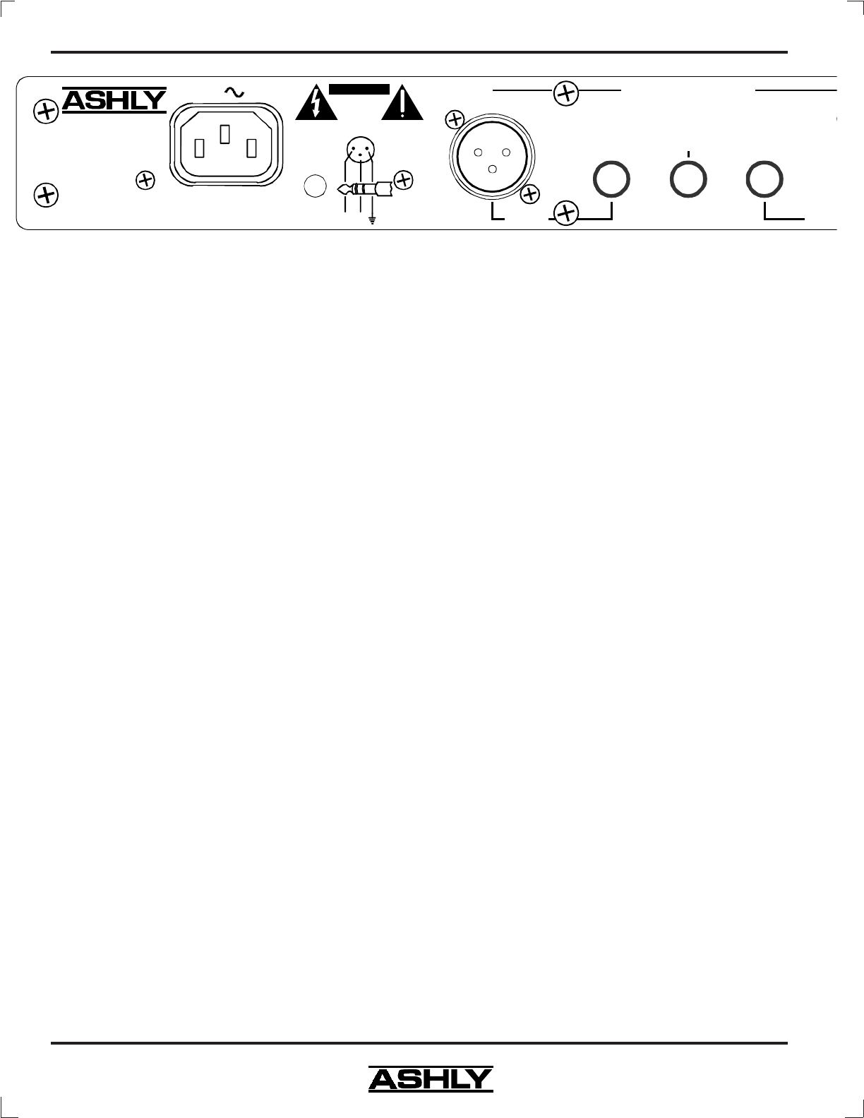
Model DPX-200
Made In USA
100-120VAC
50-60Hz 12W
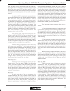
TIP = Detector Return/Ducking Input
(Use Mono Plug For Ducking)
RING = Detector Send
Output
Input
Detector
Compressor/Limiter
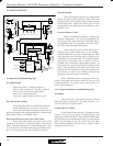
AC
Risk of Electric
Shock. Do
Not Open
CAUT ION
XLR
Female
Shown
(-)(+)
2
3
1
Mic
Phantom
Power