38
3. SETUP MENU continued …
3.11 TRIGGERS / IR / RS232
When a trigger output on the AVM 50 is connected to the trigger input of another component, such as an
amplifier or projector, the AVM 50 can turn it on or off according to the trigger’s Setup. For components that
do not have trigger inputs, a triggerable power bar may work (see your dealer).
Three 12 volt trigger outputs are provided – Trigger1 and Trigger2 each have maximum current output of
50 mA and Trigger3 has maximum current output of 200 mA. There is a quarter of a second delay between
each trigger to minimize line voltage drops caused by switching on too many devices at the same time.
All Triggers:
When ‘Disabled’ all triggers remain off. When ‘Enabled’ the trigger chart below is used to set conditions. For
custom installation, the ‘RS-232 Ctrl’ setting uses external control.
Set Trigger:
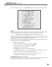
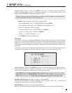
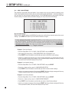
Highlighting ‘b. SET TRIGGER 1’ and then pressing SELECT displays this menu:
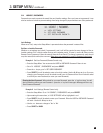
In the example shown, TRIGGER 1 activates when MAIN power is turned on. Trigger outputs can also be set
to activate according to Source selection instead of Power.
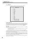
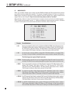
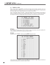
11. TRIGGER / IR / RS232
a. ALL TRIGGERS:Disabled
b. SET TRIGGER 1
c. SET TRIGGER 2
d. SET TRIGGER 3
e. SET IR-INPUTS
f. BAUD RATE: 19200
g. FLOW CONTROL: None
h. RS-232 TX STATUS: Off
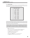
11b. SET TRIG-1 SOURCES
MAIN Z2 Z3 REC
a. POWER: * - -
b. CD : - - - -
c. 2-Ch : - - - -
d. 6-Ch : - - - -
e. TAPE : - - - -
f. FM/AM: - - - -
g. DVD1 : - - - -
h. DVD2 : - - - -
i. DVD3 : - - - -
j. DVD4 : - - - -
k. TV1 : - - - -
l. TV2 : - - - -
m. TV3 : - - - -
n. TV4 : - - - -
o. SAT1 : - - - -
p. SAT2 : - - - -
q. VCR : - - - -
r. AUX : - - - -


