


11
2. CONNECTIONS continued …
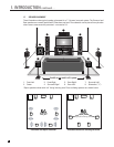
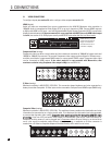
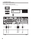
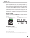
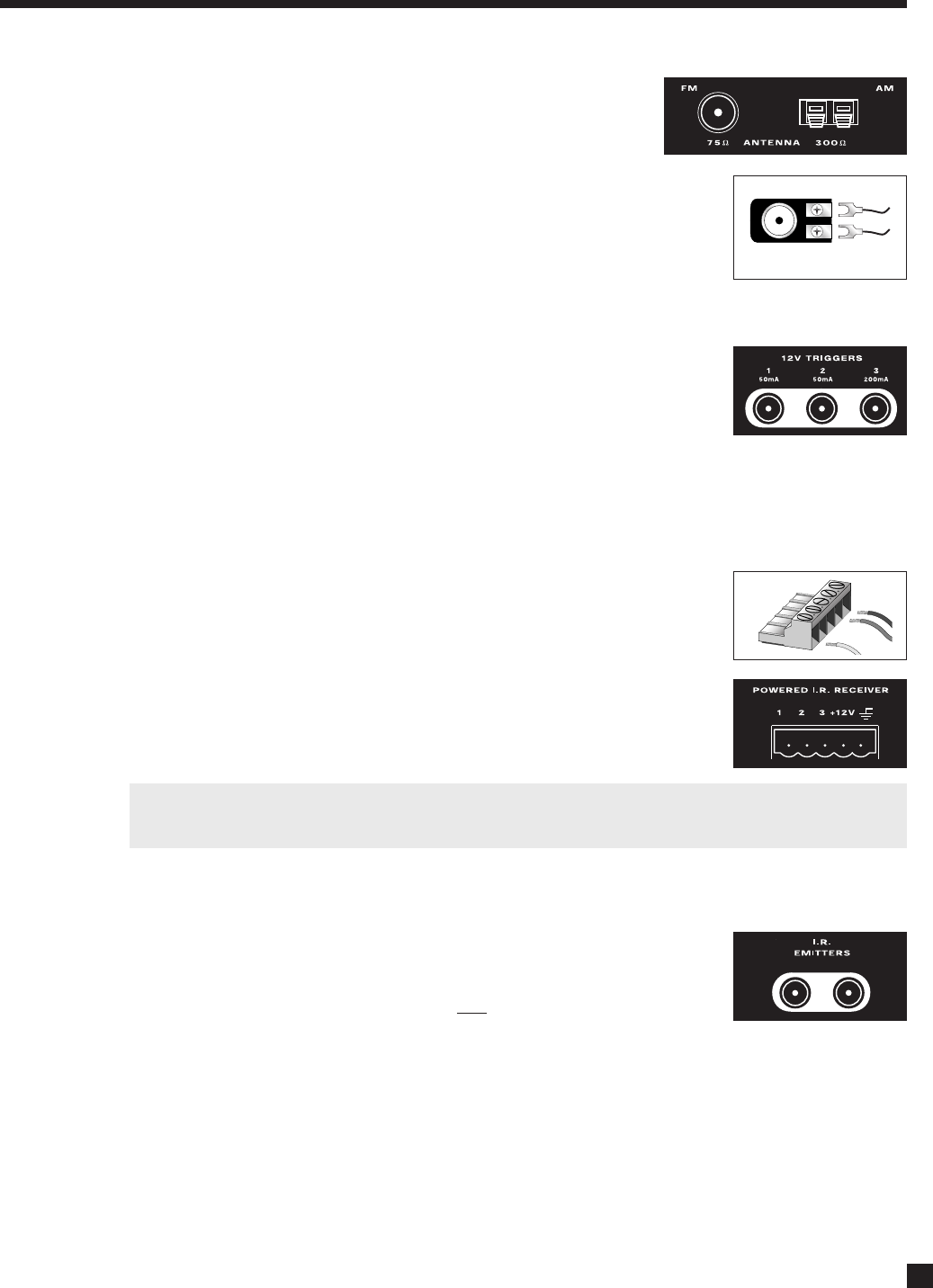
2.3 FM • AM ANTENNAS
To connect the AM loop antenna, press the spring-loaded tabs of the
AM ANTENNA connector and insert the bare ends of the two wires.
Move the antenna until best reception is found.
To connect the FM antenna, connect the two wires to the screw terminals of the
75-ohm to 300-ohm adapter, then connect the adapter to the FM ANTENNA
connector. Move the antenna until best reception is found – this is usually a “T”
formation. If your cable company provides FM service, you can connect the cable
to the AVM 50.
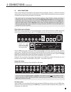
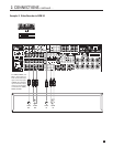
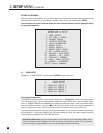
2.4 12 VOLT TRIGGERS
If your other components have provisions for a trigger, you can have them turn on
and off together with the AVM 50, or when a specified Source is selected.
Connect a trigger output from the AVM 50 to the trigger input of your power
amplifier, display, etc., using a cable with 3.5mm mono mini plugs.
The AVM 50 provides flexible trigger options. From the factory, all the triggers are disabled. Through the
Setup Menu, you can specify the conditions for enabling triggers (see section 3.11).
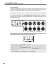
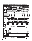
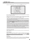
2.5 POWERED I.R. (INFRA RED) RECEIVERS
External IR receivers allow the Remote Control to be used from other locations in
your home. Once an IR receiver is wired to another room, connect it to one of the
three I.R. RECEIVER inputs through the removable terminal block. To use the
terminal block, remove it from the AVM 50, loosen the proper screw, insert the
wire in the slot, tighten the screw onto the wire, and insert the terminal block into
the AVM 50. See section 3.11 for Setup information.
In addition, there is no need for an external 12V supply to power the receivers –
use the AVM 50’s built-in supply instead for up to three IR receivers, and connect
according to the IR receiver manufacturer’s instructions.
Custom Installers: The AVM 50’s IR inputs sense modulated 38 kHz carrier, not demodulated data. With
some control systems, an emitter face-to-face with an IR receiver may be needed.
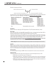
2.6 I.R. (INFRA RED) EMITTERS
External IR emitters allow control of your source components from any location in
your home that has an IR receiver wired to the back of the AVM 50. After
positioning the IR emitter according to its instructions, connect it to I.R. EMITTER
output. Commands that come in through the rear
I.R. RECEIVER connections are
re-transmitted through the IR emitters.
2.7 POWER
To connect power, use the supplied double-insulated power cord and then turn on the Rear Panel AC switch.
120 V 60 Hz
170 W MAX
EX P ANSION PORT
SHOCK HAZARD
DO N O T OPE N .
RISQUE DE CHOC ÉLECTRIQUE
NE P AS OUVRIR
MAIN AUDIO-OUT (BALANCED)
SUB 2
MAIN AUDIO-OUT
120 V 60 Hz
170 W MAX
EX P ANSION PORT
SHOCK HAZARD
DO N O T OPE N .
RISQUE DE CHOC ÉLECTRIQUE
NE P AS OUVRIR
MAIN AUDIO-OUT (BALANCED)
SUB 2
MAIN AUDIO-OUT
120 V 60 Hz
170 W MAX
EX P ANSION PORT
SHOCK HAZARD
DO N O T OPE N .
RISQUE DE CHOC ÉLECTRIQUE
NE P AS OUVRIR
MAIN AUDIO-OUT (BALANCED)
SUB 2
MAIN AUDIO-OUT
75-ohm to 300-ohm adapter
120 V 60 Hz
170 W MAX
EX P ANSION PORT
SHOCK HAZARD
DO N O T OPE N .
RISQUE DE CHOC ÉLECTRIQUE
NE P AS OUVRIR
MAIN AUDIO-OUT (BALANCED)
SUB 2
MAIN AUDIO-OUT