


43
30 31 32 33 34 39 403837
44
46
35
42
41
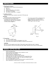
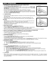
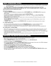
Figure 7
tinuous mode, the drive will play all the tracks on the cd and
return to cue mode after the last track has finished playing.
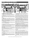
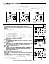
35. TOTAL INDICATOR - When total is indicated in the LCD
display the TIME DESCRIBED (47) in the LCD will define the
total combined remaining time of all the tracks on the CD.
36. REMAIN INDICATOR - in the LCD display will define the
indicated time as the time remaining on the current track.
37. BPM INDICATOR - This will indicate the measurement
displayed in BPM/PITCH METER (40) is in BPM’s.
38. PITCH INDICATOR - This will indicate the measurement
displayed in BPM/PITCH METER (40) is the amount of
Pitch percentage.
39. LOOP - Appears when LOOP is engaged. LOOP flashes
in LCD DISPLAY (8) when playing loop.
40. BPM/PITCH METER - This meter displays either the
BPM’s (beat per minute) or percentage of pitch adjustment .
The meters definition will be indicated by either BPM (37) or
PITCH (38) in the LCD display.
GENERAL FUNCTIONS AND CONTROLS (Cont.)
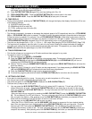
41. SAMPLE BANK INDICATORS - Indicates which samples
are stored. Note: last played sample will flash in LCD screen.
42. RELOOP INDICATOR - Appears when LOOP is engaged.
LOOP flashes in LCD DISPLAY (39) when playing loop.
43. TRACK INDICATOR - This indicator describes the current
track being played or Cued.
44. MEMORY BUCKET INDICATOR - Shows the cue memory
state if empty or full.
45. ELAPSE INDICATOR - When this indicator is on the time in
the TIME METER (47) will define the current track elapse time.
46. TIME BAR INDICATOR - Shows the time length defined in
elapse or remain.
47. TIME METER - This meter will display the elapse total, or
remain time of the CD or track. The display time will depend on
the selected function.
36
45
47
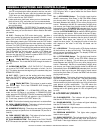
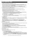
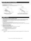
Fig. 8 (PLAYER UNIT)
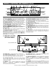
Fig. 9 (CONTROL UNIT)
51
52
54
54
50
49
53
53
48
48. DIGITAL OUT - connect to Mini disc or CD-R device.
49. POWER CONNECTOR/FUSE - Power Connector with
built-in fuse holder. Always replace with same type fuse.
50. VOLTAGE SELECTOR - Select which voltage desired:
115V or 230V. Always disconnect the power plug before
changing the voltage.
51. REMOTE 1 & 2 - Connect supplied 8-pin cable from
REMOTE 1 on MAIN UNIT to REMOTE 1 on CONTROL
UNIT (48) and same for Remote 2.
52. AUDIO OUT R & L - Audio Out signals. Connect RCA
cable from AUDIO OUT to a mixer input.
53. DRIVE UNIT REMOTE - Connect supplied 8-pin cable from
REMOTE 1 on MAIN UNIT (51) to REMOTE 1 on CONTROL
UNIT, and REMOTE 2 on the Drive Unit to Remote 2 on the
Control Unit.
54. CONTROL - Connect mini-plug from CONTROL out on rear
of CONTROL UNIT to a mixer’s CONTROL out. This feature is
available on all mixers with Fader “Q” Start (see Q” Start Control
p.5).
C. MAIN UNIT & PLAYER
UNIT REAR PANELS
American DJ® AUDIO • DCD-PRO500™ INSTRUCTION MANUAL • PAGE 8