


25-EN
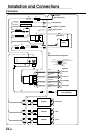
1 ISO Antenna Convertor Plug
2 Antenna Receptacle
Connect to the supplied ISO antenna convertor plug.
3 Audio Interrupt In Lead (Pink/Black)
Connect this lead to the Audio Interface output of a cellular
phone which provides ground shorting when a call is
received.
If a device having the interrupt feature is connected, audio
will be automatically muted whenever the interrupt signal is
received from the device.
4 Remote Turn-On Lead (Blue/White)
Connect this lead to the remote turn-on lead of your
amplifier or signal processor.
5 Switched Power Lead (Ignition) (Red)
Connect this lead to an open terminal on the vehicle’s fuse
box or another unused power source which provides (+) 12V
only when the ignition is turned on or in the accessory
position.
6 Power Antenna Lead (Blue)
Connect this lead to the +B terminal of your power antenna,
if applicable.
NOTE
This lead should be used only for controlling the vehicle's power
antenna. Do not use this lead to turn on an amplifier or a signal
processor, etc.
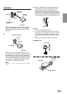
7 Ground Lead (Black)
Connect this lead to a good chassis ground on the vehicle.
Make sure the connection is made to bare metal and is
securely fastened using the sheet metal screw provided.
8 Fuse Holder (15A)
9 Battery Lead (Yellow)
Connect this lead to the positive (+) post of the vehicle’s
battery.
! ISO Power Supply Connector
" Remote Control Interface Connector
To remote control interface box.
# DIN Connector
Connect this to the DIN connector on the CD changer.
$ Power Supply Connector
% Left Rear (+) Speaker Output Lead (Green)
& Left Rear (–) Speaker Output Lead (Green/Black)
( Left Front (+) Speaker Output Lead (White)
) Left Front (–) Speaker Output Lead (White/Black)
~ Right Front (–) Speaker Output Lead (Grey/Black)
+ Right Front (+) Speaker Output Lead (Grey)
, Right Rear (–) Speaker Output Lead (Violet/Black)
- Right Rear (+) Speaker Output Lead (Violet)
. ISO Connector (Speaker Output)
/ DIN Extension Cable (Included with CD changer)
NOTE
Older Alpine CD changer came with standard, straight type DIN
connectors. In installations where an L-type connector would
simplify installation, the Alpine 4910
02
Adaptor can be used
(sold separately).
: Subwoofer Output RCA Connectors
RED is right and WHITE is left.
; Rear Output RCA Connectors
RED is right and WHITE is left.
< Front Output RCA Connectors
RED is right and WHITE is left.
= RCA Extension Cable (sold separately)
To prevent external noise from entering the audio system.
• Locate the unit and route the leads at least 10
cm away from the car harness.
• Keep the battery power leads as far away from other leads as possible.
• Connect the ground lead securely to a bare metal spot (remove any paint, dirt or grease if necessary) of the car chassis.
• If you add an optional noise suppressor, connect it as far away from the unit as possible. Your Alpine dealer carries various noise
suppressors, contact them for further information.
• Your Alpine dealer knows best about noise prevention measures so consult your dealer for further information.