


ALPINE PDR-V75 68-25285Z56-A (EN/FR/ES)
7-EN
EN
FR
ES
CAUTION
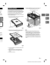
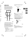
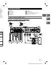
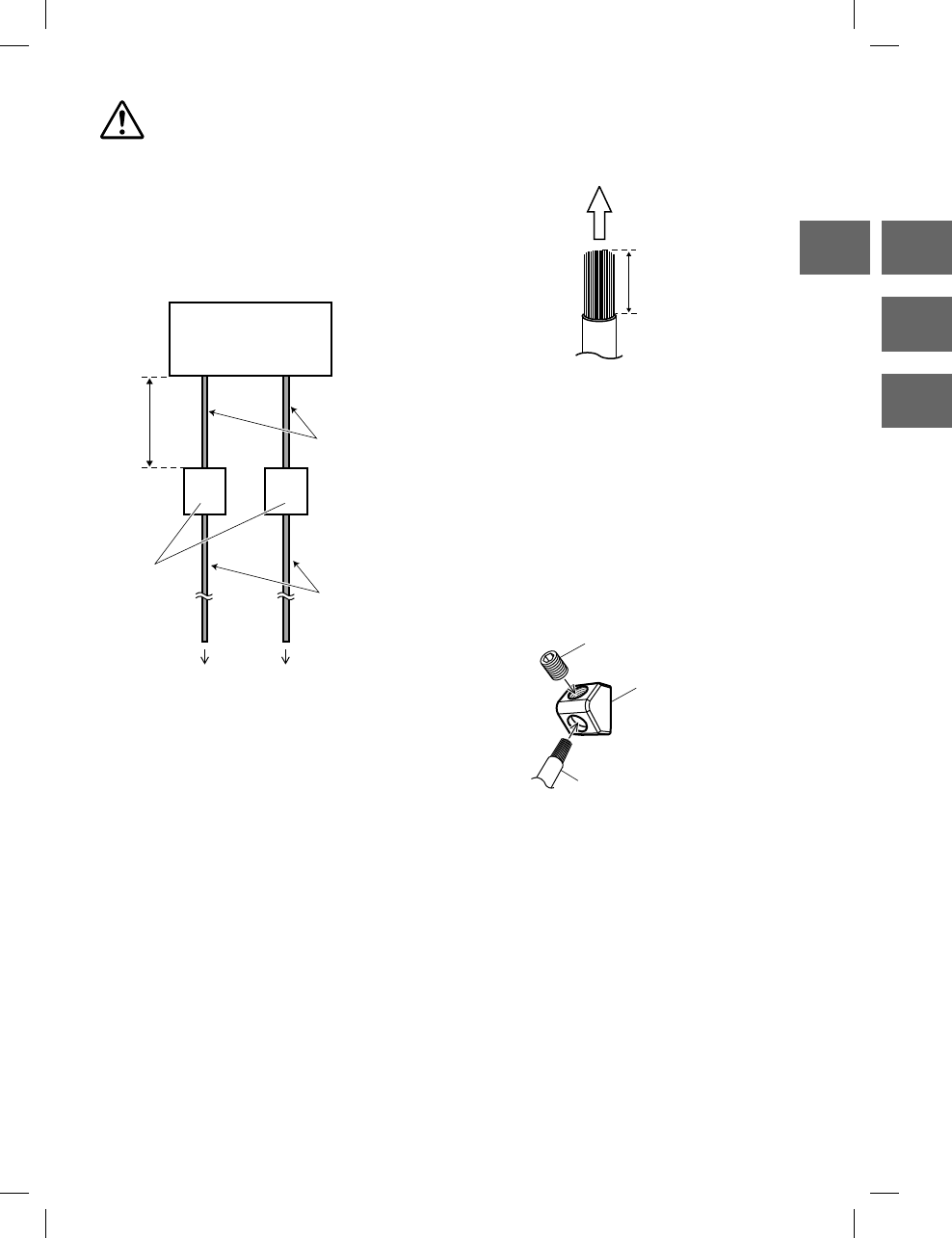
About Power supply wires
If the length of the power and ground cables
exceed 1 m, or if you connect more than one
amplifier, a distribution block should be used. See
below for wire gauge recommendations for
distribution block connection to battery and
ground (depends upon wire length necessary):
2 AWG (33 mm
2
) or 1/0 AWG (53 mm
2
)
PDR-V75
BATTERY GROUND
4 AWG
(21 mm
2
)
Distribution
block
1 m
(Max.)
2 AWG (33 mm
2
) or
1/0 AWG (53 mm
2
)
To vehicle’s
battery
To vehicle’s
chassis
Fig. 6
Connect all equipment to the same ground point while
keeping wire length as short as possible.
Ensure that you install a correctly-rated in-line fuse
on the power cable near the battery positive post.
Cautions on wire lead connections
When using third-party wire cables (power supply
wire), use the supplied screws to simplify the
connection. Refer to the description below for the
proper procedure. If you are in doubt about how to
make this connection, consult your dealer.
1. Check the wire size.
• Required Wire Size
–Battery Lead/Ground Lead ....4 AWG (21 mm
2
)
–Remote Turn-On Lead .............12 AWG (3 mm
2
)
–Speaker Output Lead:
SUB W. .............................................8 AWG (8 mm
2
)
CH-1/2/3/4 ..................................12 AWG (3 mm
2
)
• If the wire gauge used is unknown, ask your
dealer.
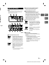
2. Remove the insulation from the ends of the wire
leads by about 7 – 10 mm (9/32” – 13/32”).
(Fig. 7)
Lead end side of the product
7 – 10 mm
(9/32” – 13/32”)
Fig. 7
NOTES:
• If length of the exposed wire is too short, a poor
connection may occur causing operation failure
or sound interruption.
• On the other hand, if the length is too long, an
electrical short-circuit may occur.
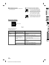
3. Tighten the set screw with the hexagon wrench
(included) to secure the lead. (Fig. 8)
Before making this connection, use insulated
shrink tubing to cover any exposed wire
extending beyond the terminal.
Hexagon Screw
Wire Terminal
Wire
Fig. 8
NOTES:
• Use only the screws included.
• For safety reasons, connect the battery leads last.
• To prevent disconnection of the leads or
dropping of the unit, do not use the cabling to
carry the unit.
a
ttery
positive
e
hicle’s
t
. See
nimum
/
21 mm
2
r
e metal
p
oint to
u
ity
all your
n
the
e
eping
/
21 mm
2
y
)
u
r head
a
ble, see
eads of
y
ou do
o
n lead,
i
on of
N
G”
t
he
e
,
y