


ALPINE PDR-V75 68-25285Z56-A (EN/FR/ES)
9-EN
EN
FR
ES
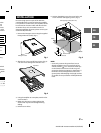
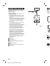
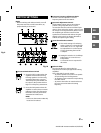
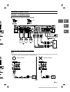
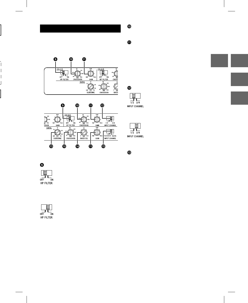
SWITCH SETTINGS
NOTE:
• Before switching each Selector Switch, turn off
the power and insert a small screwdriver, etc.,
perpendicularly to the Switch.
Fig. 10
Crossover Mode Selector Switch
a) Set to the “OFF” position when the
amplifier will be used for driving
full range speakers or when using
an external electronic crossover.
The full frequency bandwidth will
be output to the speakers with no
high or low frequency attenuation.
b) Set to the “ON” position when the
amplifier is used to drive a tweeter/
midrange system. The frequencies
below the crossover point will be
attenuated at 12 dB/octave.
NOTE:
• In this case the maximum Bass EQ
boost level is reduced.
Crossover Frequency Adjustment Knob
Use this control to adjust the crossover
frequency between 50 and 400 Hz.
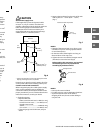
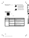
Input Gain Adjustment Control
Set the PDR-V75 input gain to the minimum
position. Using a dynamic CD as a source,
increase the head unit volume until the output
distorts. Then, reduce the volume 1 step (or until
the output is no longer distorted). Now, increase
the amplifier gain until the sound from the
speakers becomes distorted. Reduce the gain
slightly so the sound is no longer distorted to
achieve the optimum gain setting.
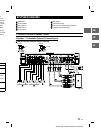
Input Channel Selector Switch
a) This switch setting is for selecting
either 2-channel or 4-channel input
mode. When set to “1/2”, signal will
be copied from CH-1/2 and sent to
CH-3/4, eliminating the need for
Y-adapters.
b) Setting this switch to “3/4” will keep
both inputs, CH-1/2 and CH-3/4
independent.
A 4-channel source is required for
this mode.
Subsonic Filter
The subsonic filter for cutting ultra low
frequencies from the input signal before being
amplified.
This is desirable for several reasons:
–To protect speakers too small or not capable
of reproducing ultra low frequencies.
–To minimize power wasted from reproducing
inaudible sound.
–To protect subwoofers in vented enclosures
from over excursion below the tuning
frequency.
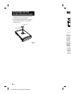
Fig. 9