


ALPINE PDR-V75 68-25285Z56-A (EN/FR/ES)
6-EN
C
About P
If the le
n
exceed 1
amplifie
r
below f
o
distribut
ground
(
2 AWG (
3
Distribu
block
1 m
(Max.)
Connec
t
keepin
g
Ensure t
h
on the p
o
Caution
s
When u
s
wire), us
e
connect
i
proper
p
make th
i
1. Chec
k
• Req
–B
a
–R
e
–S
p
S
U
C
H
• If th
dea
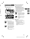
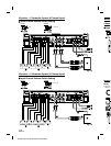
Speaker Output Terminals
• The speaker output terminals of this unit are
insert terminal.
Be sure to observe correct speaker output
connections and polarity in relation to the other
speakers in the system. Connect the positive
output to the positive speaker terminal and the
negative to negative.
About Subwoofer Input/Output Terminals
• The input is stereo but the output is monaural.
• Reversing subwoofer polarity may be desirable
in some installations for optimum bass
performance.
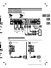
About Bridged Connections
In the bridged mode, connect the left positive to
the positive terminal on the speaker and the
right negative to the negative terminal of the
speaker. Do not use the speaker (–) terminals as
a common lead between the left and right
channels.
Use a Y-adapter (sold separately) for the input
when bridging the outputs. (Refer to the
“BRIDGED CONNECTIONS” on page 13.)
NOTE:
• Do not connect the speaker (–) terminal to the
vehicle’s chassis.
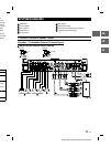
RCA Input Jacks
Connect these jacks to the line out leads on your
head unit using RCA extension cables (sold
separately). Be sure to observe correct channel
connections; Left to Left and Right to Right.
Fuse
PDR-V75 ...............................................................40 A x 2
USE THE CORRECT AMPERE RATING WHEN
REPLACING FUSES.
Failure to do so may result in fire or electric
shock.
Power Supply Terminal
Remote Bass Control (Option)
Connect the Remote Bass Control Unit (sold
separately) to adjust the output level remotely.
This is not to replace appropriate gain level
setting between the amplifier and head unit.
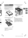
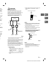
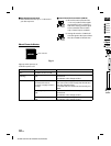
Battery Lead (Sold Separately)
Be sure to add an in-line fuse with the battery
lead as close as possible to the battery’s positive
(+) terminal. This fuse will protect your vehicle’s
electrical system in case of a short circuit. See
below for appropriate fuse value and minimum
wire gauge requirement:
PDR-V75 .....................80 amp fuse, 4 AWG/21 mm
2
Ground Lead (Sold Separately)
Connect this lead securely to a clean, bare metal
spot on the vehicle’s chassis. Verify this point to
be a true ground by checking for continuity
between that point and the negative (–)
terminal of the vehicle’s battery. Ground all your
audio components to the same point on the
chassis to prevent ground loops while keeping
wire length as short as possible.
Minimum required wire gauge for this
connection is as follows:
PDR-V75 ................................................4 AWG/21 mm
2
Remote Turn-On Lead (Sold Separately)
Connect this lead to the remote turn-on
(positive trigger, (+) 12V only) lead of your head
unit. If a remote turn-on lead is not available, see
“CONNECTION CHECK LIST” section on
page 8 for alternative method.
NOTE:
• When connecting the speaker output leads of
the head unit to this unit with an RCA
extension cable (sold separately), etc., you do
not need to connect the remote turn-on lead,
owing to the “REMOTE SENSING” function of
this unit. However, the “REMOTE SENSING”
function may not work depending on the
signal source connected. In such a case,
connect the remote turn-on lead to an
incoming power supply cord (accessory
power) in the ACC position.