Model MRC44 Page: 7
© 2002 Xantech Corporation
MRC44 CONTROLLER/AMPLIFIER PANEL AND FEATURE DESCRIPTIONS
FOUR ZONE - FOUR SOURCE AUDIO/VIDEO CONTROLLER/AMPLIFIER
MRC44
1234
POWER
4
1
2
3
2
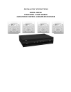
Figure 2 – The Model MRC44 Controller/Amplifier – Front Panel Features and Functions
1. Front Panel.
2. Chassis Feet. Set high enough to provide through-chassis cooling by natural convection.
3. Master AC Line On/Off Switch. Turns AC power On/Off to the entire unit.
4. Power and Status LED Indicators. Four indicators, one for each Zone, provide the following status
information:
System Status (Power-Up Mode)
a) Slow Orange Blink – indicates general initialization is occurring.
b) Fast Green Blink – indicates that a keypad on the associated zone is currently being initialized.
c) Fast Red Blink – indicates that the master keypad on the associated zone is not responding to
initialization.
d) Fast Orange Blink – indicates that the slave keypad on the associated zone is not responding to
initialization.
e) All Lights Off – initialization is done, system is ready for operation.
Zone Status (Operational Mode)
a) Steady Green to indicate that Zone is in the Power-Up Mode, is not muted and is not within 5 dB of
MAX-V.
b) Steady Red to indicate that Zone is in the Power-Up Mode, is not muted and is within 5 dB of MAX-V.
c) Flash Green to indicate that Zone is in the Power-Up Mode, is muted and is not within 5 dB of MAX-V.
d) Flash Red to indicate that Zone is in the Power-Up Mode, is muted and is within 5 dB of MAX-V.
e) Flash Green to indicate that Zone is in the Power-Up Mode, is not muted, is not within 5 dB of MAX-V
and is being Ramped Up or Down.
f) Flash Red to indicate that Zone is in the Power-Up Mode, is not muted, is within 5 dB of MAX-V and is
being Ramped Up or Down.
g) Off to indicate that Zone is in the Power-Down Mode.