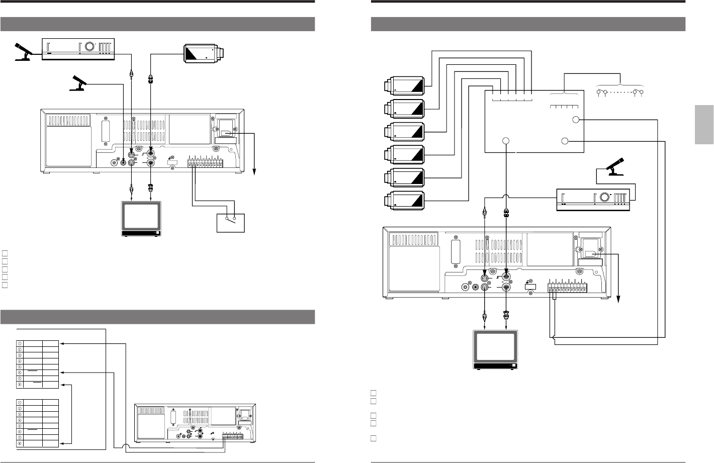
3-1 Connecting to a Camera
3 CONNECTIONS
Microphone
Amplifier
RCA
BNC
Microphone
M3.5 mini-
jack
Video camera
RCA
BNC
ALARM INCOM
AC 120 V
50/60 Hz
Provided
power cable
Alarm sensor
Monitor TV
Connect the monitor
’s video/audio input connectors to the SR-9080
’s video/audio output connectors.
Connect the video camera
’s video output connector to the SR-9080
’s video input connector.
Input audio signals to the audio input connectors via an amplifier.
When connecting an alarm sensor, connect it to the SR-9080
’s alarm input terminal.
When the connection is complete, connect the power plug to an AC 120 V : U model, AC 220 - 240 V : E model, 50/60 Hz
outlet.
CONNECTION TO THE SW-501/SW-502 SEQUENTIAL SWITCHER
1.
Connect pin 6 on the sequential switcher's TIMER INPUT
connector to the VCR's CAMERA SW OUT terminal. Connect
pin 1 to the GND terminal.
2. Connect pin 8 on the sequential switcher's TIMER INPUT
connector to pin 8 on its TIMER OUT connector.
Note:
● Be sure to use two DIN connectors for connections.
COM
CAMERA SW OUT
3-2 System Using Sequential Switcher
Connect video cameras and alarm sensor to a sequential switcher (frame switcher).
Connect the sequential switcher
’s (frame switcher) alarm signal output, camera switching signal input and video output to
the SR-9080.
Connect the monitor
’s video/audio input connectors to the SR-9080
’s video/audio output connectors.
When the connection is complete, connect the power plug to an AC 120 V : U model, AC 220 - 240 V : E model, 50/60 Hz
outlet.
Synchro should be applied to all connected video cameras.
Video camera
Alarm sensor input
Alarm sensor
Microphone
Alarm signal output
Camera switching
signal input
Sequential switcher
BNC
RCA
Amplifier
Monitor TV
RCA
AC 120 V
50/60 Hz
3 CONNECTIONS
Provided
power cable
CAM SW
OUT
ALARM IN
BNC
Video output