(023-100 intentionally excluded)
Diagnostic Tests 5-21
103 Communication Loop-back Test (Single Loop)
1 Remove the interface cable from the printer.
2 Check to make sure the four DIP switches on the signal interface board have been
pulled toward the printer’s back cover. Close the back cover.
3 Install the RS-232C and RS-422 loop-back connectors, found in the tool kit mounted
inside the right printer cover.
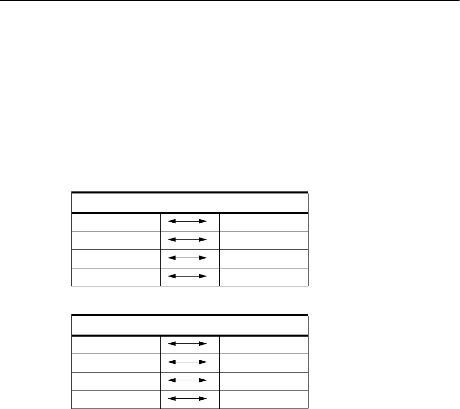
If you do not have loop-back connectors, jumper the connections as outlined in Table
5-24, “RS-232 Loopback Connections” and Table 5-25, “RS-422 Loopback Connec-
tions”.
4 Go to: 103
5 Press: READY to run the test.
6 If an error code appears, check the “Error Code/TAG Cross-Reference” on page 2-3
to determine which TAG to follow.
7 If no error is detected, the test exits automatically.
8 Press: STOP to exit, if an error is detected. (For some errors, you may have to power-
on-reset the printer.)
9 Remove the wrap connectors.
10 Reinstall the interface cable.
Table 5-24. RS-232 Loopback Connections
RS-232 Loopback Connection Reference
pin 2 pin 3
pin 4 pin 5
pin 8 pin 20
pin 17 pin 24
Table 5-25. RS-422 Loopback Connections
RS-232 Loopback Connection Reference
pin 2 pin 4
pin 9 pin 11
pin 7 pin 6
pin 14 pin 13


