EPSON Stylus Color 900 Revision C
Troubleshooting Overview 91
Table 3-19.
Isolating the Faulty Part on the Power Supply Board (continued)
Table 3-20.
Isolating the Faulty Part on the Power Supply Board (continued)
Step Check Point Action
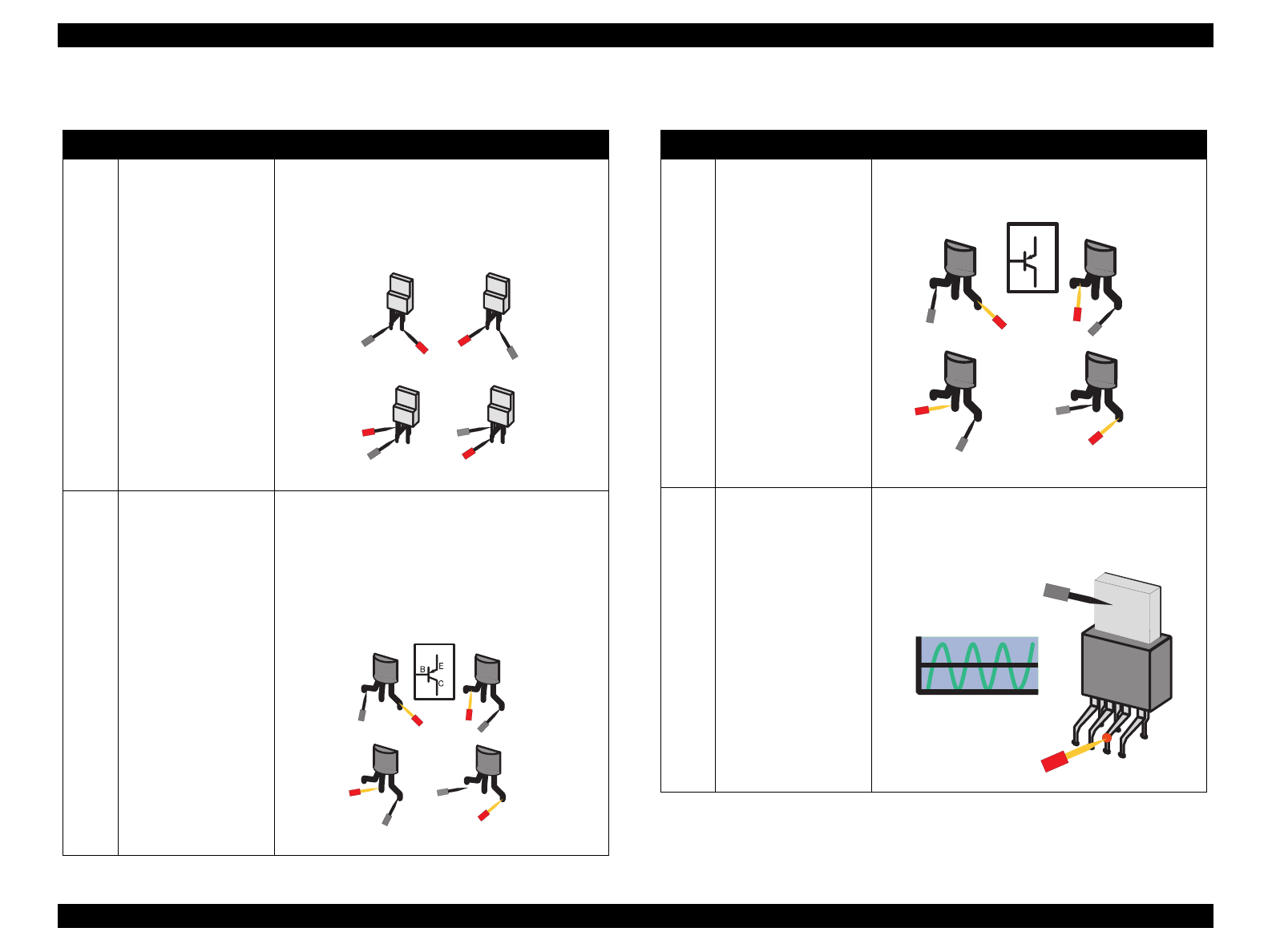
9 Is the main switching
FET (Q1) defective?
Check the electrical continuity of the switching
FET by trying four patterns below. Be sure to pay
attention to the polarity. If the main switching FET
is good, the findings should be as shown under the
figure.
Step 1: Off, Step 2: On, Step 3: Off, Step 4: Off
10 Is the NPN connection
transistor defective?
Check the electrical continuity of the NPN
connection transistor on the C265 PSB/SE board
by trying four patterns below. Be sure to pay
attention to the polarity. If the NPN contact
transistor is good, the findings should be as shown
under the figure. Note the NPN connection
transistor is shown in the circuit diagram as
described below.
Step 1: On, Step 2: Off, Step 3: Off, Step 4: On
Step.1
G
D
S
+
-
Step.2
G
D
S
+
-
Step.3
G
D
+
-
Step.4
G
D
+
-
Step.1
+
+
Step.2
+
+
-
NPN Tr
Step.3
Step.4
B
C
E
B
C
E
B
C
E
B
C
E
-
-
-
Step Check Point Action
11 Is the PNP connection
transistor defective?
Check the PNP connection transistor on the C265
PSB/SE board in the same manner described in
the previous step.
Step 1: Off, Step 2: On, Step 3: Off, Step 4: On
12 Is the +5 V regulator
(IC51) defective?
Check the IC51 for the oscillation waveform
(measured by using a oscillo scope) output from
the Pin 5. If the output waveform is as shown
below, it means the IC51 is working properly.
Step.1
+
-
+
-
Step.2
+
-
+
-
B
E
C
PNP Tr
Step.3
Step.4
E
B
C
E
B
C
E
B
C
E
B
C
5-pin(O SC )
GND
IC 5 1
O s c illa tio n w a v e fo rm


