EPSON Stylus Color 900 Revision C
Maintenance Lubrication and Adhesion 168
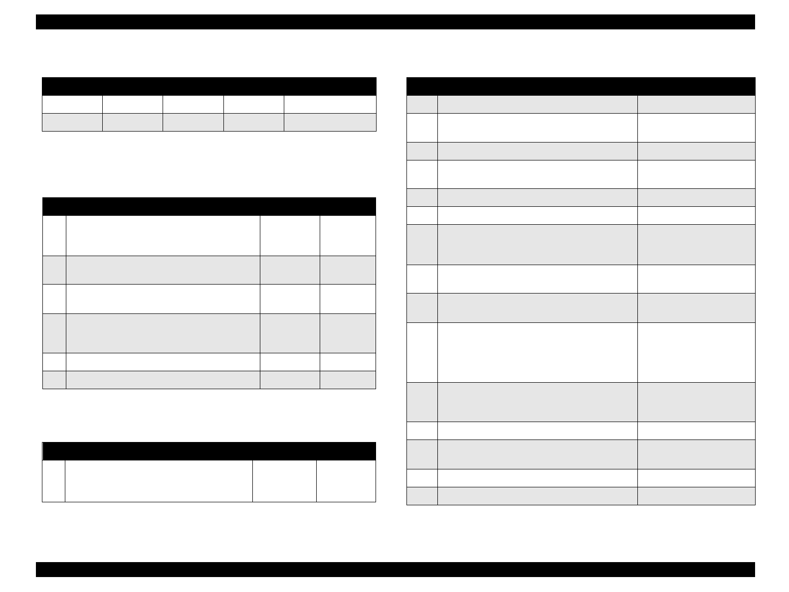
Table 6-2. Oil Applied to the Stylus Color 900
NOTE:
No adhesion is used in the Stylus Color 900.
Table 6-3. Lubrication Points Using G-26
Table 6-4. Lubrication Point Using the O-8
Table 6-5. Lubrication Points
Type Part name Content Part code Availability
Grease G-26 40g B702600001 EPSON exclusive
Oil O-8 40g 1019753 EPSON exclusive
No.
Lubricating Point
Amount Ref. figure
1
Using a brush, lubricate the whole inner
surface of the round cutout in the right side of
the [Frame,ASF;B].
φ
1 x 1 mm
Figure 6-8
2
Using a brush, lubricate right and left sides of
the [Hopper ASSY, C].
φ
1 x 2 mm
Figure 6-9
3
Lubricate the inner gear of the [Combination
gear,14.4, 24].
φ
1 x 1 mm
Figure 6-10
4
Lubricate the surface of the bearing part (the
round cut) of the [Bushing,12] located at the
right end of the printer mechanism.
φ
1 x 10 mm
Figure 6-11
5 Lubricate the [Shaft, Pulley, Driven].
φ
1 x 1 mm
Figure 6-12
6 Lubricate the back of the [Frame, Guide, CR].
φ
1 x 150 mm
Figure 6-13
No.
Lubricating Point
Amount Ref. figure
1
Apply oil to the [Oil Pad].
Before lubricating, observe the CAUTION in
Section 6.2 well.
0.7 - 0.75 cc Figure 6-14
No.
Lubricating Point
Amount
1 The shaft in the [Frame Assembly, DE, Right] G-26 (
φ
1 x 10 mm)
2 The teeth of the [Gear, 25.8] G-26
(
φ
1mm x 1/3 of the circle)
3 The shaft in the [Frame Assembly, DE, Left] G-26 (
φ
1 x 10 mm)
4 The teeth of the smaller gear in the
[Combination Gear,12, 26]
G-26
(
φ
1mm x 1/3 of the circle)
5 12 points on the [Paper Guide,Front] G-26 (
φ
1 x 2 mm)
6 4 points in the [Grounding Plate,Paper Eject] G-26 (
φ
1 x 2 mm)
7 2 contact areas; between [Roller
Assembly,Paper Eject, Rear] and [Grounding
Plate, Eject]
G-26 (
φ
1 x 2 mm)
8 2 contact areas; [Roller Assembly, Eject] and
[Grounding Plate, Eject]
G-26 (
φ
1 x 2 mm)
9 The teeth of the right and left [Gear,27]s G-26
(
φ
1mm x 1/4 of the circle)
10 2 points on the shaft in the [Lever Assembly,
Release,Cam]
NOTE: Do not apply lubricant to the roller
surface.
G-26 (
φ
1 x 2 mm)
11 [Oil Pad]
Refer to Section 6.2.1 “Lubricating the Carriage
Guide Shaft”.
O-8 (0.7 - 0.75 cc)
12 A hole in the [Frame Assembly, Middle, Left] G-26 (
φ
1 x 3 mm)
13 Roller shaft in the [Lever Assembly, Roller
Release, Right]
G-26 (
φ
1 x 1 mm)
14 Pin on the [Frame, Middle, Right] G-26 (
φ
1 x 3 mm)
15 Narrow end of the [Shaft, Arm Lifter] G-26 (
φ
1 x 2 mm)


