


9
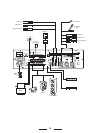
aremeantfortheconnectionofcondensertypemicrophonesthatuse24Vphantom
power,dynamicmicrophones(30-600ohms)orahighlevelsoundsource(e.g.AM/
FMtuner,cassettedesk,CDplayer,etc.).Incaseyouareusingitisnecessarytouse
theswitch(26).
Note:Connectingunbalancedmicrophonestotheamplierwhenthephantomis
switchedoncouldleadtoseveredamageonthemicrophonesandisthereforenot
recommended.Itisabsolutelymandatorytoperformanypluggingorunpluggingof
microphonecableswiththephantompowerturnedoff.Also,makesurethatthephan-
tompoweristurnedoffwhenusingmicrophonesthatarenotmeanttobeoperated
withphantompower.Thevoltageispresentonpin2andpin3oftheXLR-connector
couldleadtoseveredamagesonthemicrophones.Whenindoubt,pleaseconsult
theowner’smanualofthequestionablemicrophoneorcontactyourdealerbeforeyou
performanyconnections.
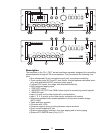
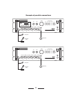
24. AM Loop Antenna (CA1T Only)
ThisantennaforreceivesAMfrequencybandwaves.
25. FM Antenna (CA1T Only)
ThisantennaforreceivesFMfrequencybandwaves.
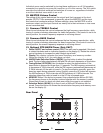
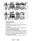
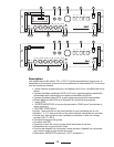
26. INPUT 2, INPUT 3 and INPUT 4 lnputs Sensitivity and XLR
Phantom Power 24V Switch
ByturningtheseswitchstotheLINEpositionINPUT2,INPUT3andINPUT4canbe
connectedtoanaudiosourcewithhighlevelsignaloutput.Byturningtheseswitches
totheMICpositiontheINPUT2,INPUT3andINPUT4canbeconnectedtoady-
namicmicrophonewithlowimpedance.Byselectingtheswitchtothe24Vposition,
connectsthe24VphantomsupplyontheXLR(pin2andpin3)ofINPUT2,INPUT3
andINPUT4.Thisisnecessarytooperatecondensertypemicrophoneswhichrequire
thistypeofexternalsupply.
Itisrecommendedtousethisswitchwiththemastervolumesettominimum.
27. lnput Sensitivity Switch (AUX1, AUX2)
Bysettingtheseswitchesontothe“1”positiontheAUX1andAUX2inputsaresuit-
ableforconnectingaCD-player.Bysettingtheseswitchesontothe“2”positionthe
AUX1,AUX2inputissuitableforconnectinganAM/FMradiosignaloutput.Bysetting
theseswitchesontothe“3”position,theAUX1,AUX2inputaresuitableforconnecting
toadesktopcassetteplayersignaloutput.Bysettingtheseswitchestothe“4”posi-
tion,theAUX1,AUX2inputaresuitableforconnectedhigh-levelsignaloutputs.
28. Telephone Paging Input Level Control
Thiscontrolallowsyoutosetthevolumeofthesoundsourcethatisconnectedtothe
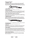
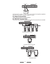
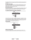
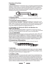
3-pin XLR
(seen from the soldered side)
Balanced
Microphone
12
3
3-pin XLR
(seen from the soldered side)
Unbalanced
Microphone
12
3
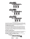
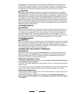
Stereo Jack (TRS)
Balanced
Microphone
Unbalanced
Microphone
1/4-inch Mono Phone Plug