


4
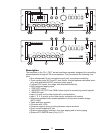
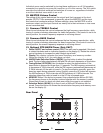
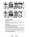
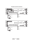
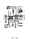
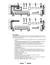
Controls and Functions
1. CHANNEL 1 Input
Thisunbalancedinputletsyouconnectalow-impedancedynamicmicrophone(30-600
ohms).Theconnectoruses6.3mmphonejack.TheinputfeaturesVOICEPRIORITY,
whichoverridesallotherinputsignalsonceamicrophonemessageissensed.Ifyouwant
tohavethisfunctiondisabledpermanently,pleasecontactaYorkvilleSoundServiceCenter.
2. MUTE Switch
ThisswitchletsyouturnVOICEPRIORITYonoroffforINPUT1(1).
3. Input Level Controls
Thesecontrolsletyouindividuallysetthevolumeofthesoundsourcethatisconnect-
edtoINPUT1,INPUT2,INPUT3,INPUT4,AUX1andAUX2/TAPE.Turningthe
controlclockwiseincreasesthevolumeofthecorrespondingsource.Werecommend
toleavethecontrolsoftheinputsnotusedtotheirminimalsettingof“0.”
4. Music Signal Monitor Output Level Control
Thiscontrolletsyousetthevolumeofthesoundoutputthatisconnectedtothe
MONITOROUTPUT(5)and1W/8Ω(31).Turningthecontrolsclockwiseincreases
thevolumeofthecorrespondingsource.
5. MONITOR Output
ThisallowsthesignaloutputoftheAUX1,AUX2/TAPE,CASSETTEandTUNERtobe
monitored.Itcanbeusedtocontrolanaudioappliancewithinputwithimpedanceover
600ohms(e.g.earphoneoranadditionalamplieretc.).Theoutputsignaliscontrolledonly
bythevolumecontrolsoftheAUX1,AUX2/TAPE,TUNERandmusicsignallevelcontrol
(4).Thisfunctionalsobehavesasatoggleswitchforthe1W/8Ω(31)additionalloudspeaker.
6. POWER Switch
UsingthePOWERswitchletsyouturnthemainpoweronoroff.
7. Indicator
Whenswitchingtheamplier’spoweron,thePeak/Limiterindicatorlightsmomentari-
ly.Whentheamplier’soutputoverloads,theOVERLOADindicatorlightsandinter-
ruptstheoutput.Forbestequipmentlife,adjustthevolumetoalowersetting.
8. LED VU-Meter
ThisLEDindicatordisplaysthesignal’soutputlevel.Forproperoperationoftheam-
plier,acorrectvolumesettingisofmajorimportance.ThersteightLEDsegments
onthelowerportionrepresenttheareabetween-20dBand0dB,inwhichtheoutput-
tedlevelshouldbekept.Ifthelasttwosegmentsontheupperportionarelitforalong
periodoftime,thismeansthattheoutputsignalisbeingdrivenintoclipping(which
usuallyresultsinaudibledistortion).Youneedtoadjustthevolumetoalowersetting.
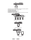
9. Zone Selection Switches
Speakerlinesofeachzone(Z1~Z4)canbeconnectedordisconnectedindepen-
dently.Toconnectthespeakerlines,turntheswitchon.Todisconnectthespeaker
lines,turntheswitchoff.
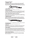
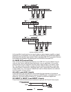
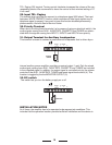
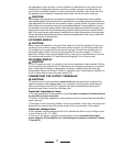
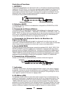
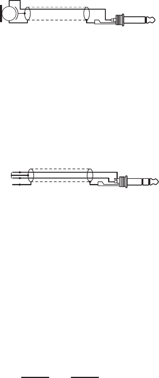
1/4-inch Mono Phone PlugUnbalanced Microphone
Earth
Symetrical
Signal
Stereo Jack (TRS)