


YMF744B
February 3, 1999
-25-
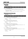
4E-4Fh: DS-1S Power Control 2
Read / Write
Default: 0000h
Access Bus Width: 8, 16, 32-bit
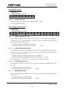
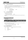
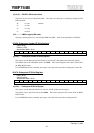
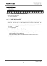
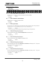
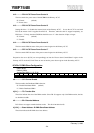
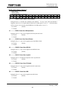
b15 b14 b13 b12 b11 b10 b9 b8 b7 b6 b5 b4 b3 b2 b1 b0
- - -
PSHWV
PSIO PSACL PSDIR PSDIT PSZV PSSRC PSPCA PSJOY PSMPU PSSB PSFM CMCD
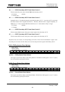
b0................CMCD: CODEC Master Clock Disable
Setting this bit to “1” disables the oscillation of the CMCLK. To stop a clock, when the CMCLK is
supplied to the AC’97, it is required that b13:PR5 bit of 4A-4Bh register is set to “1”. (If the Secondary
AC’97 is used, it is also necessary that b5:SPR5 bit of 5A-5Bh register is set to “1”.)
“0”: Normal (default)
“1”: Disable
b1................PSFM: Power Save FM Synthesizer
Setting this bit to “1” stops a clock supplied to the FM synthesizer block.
“0”: Normal (default)
“1”: Disable
b2................PSSB: Power Save Sound Blaster
Setting this bit to “1” stops a clock supplied to the Sound Blaster block.
“0”: Normal (default)
“1”: Disable
b3................PSMPU: Power Save MPU401
Setting this bit to “1” stops a clock supplied to the MPU401 block.
“0”: Normal (default)
“1”: Disable
b4................PSJOY: Power Save Joystick
Setting this bit to “1” disables the comparator of the Joystick block.
“0”: Normal (default)
“1”: Disable
b5................PSPCA: Power Save PCI Audio
Setting this bit to “1” stops a clock supplied to the PCI Audio block.
“0”: Normal (default)
“1”: Disable
b6................PSSRC: Power Save SRC
Setting this bit to “1” stops a clock supplied to the SRC block.
“0”: Normal (default)
“1”: Disable