


YMF744B
February 3, 1999
-12-
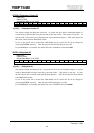
b6................PER: Parity Error Response
This bit enables DS-1S responses to Parity Error.
“0”: DS-1S ignores all parity errors.
“1”: DS-1S performs error operation when DS-1S detects a parity error.
b8................SER: SERR# Enable
This bit enables DS-1S to drive SERR#.
“0”: Do not drive SERR#. (default)
“1”: Drives SERR# when DS-1S detects an Address Parity Error on normal target cycle or a Data Parity
Error on special cycle.
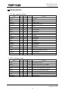
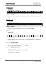
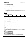
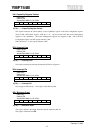
06-07h: Status
Read / Write Clear
Default: 0210h
Access Bus Width: 8, 16, 32-bit
b15 b14 b13 b12 b11 b10 b9 b8 b7 b6 b5 b4 b3 b2 b1 b0
DPE SSE RMA RTA STA DEVT DPD - - - CAP - - - -
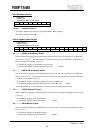
b4................CAP: Capability (Read Only)
This bit indicates that DS-1S supports the capability register. This bit is read only. When 58-59h :
ACPI Mode register, ACPI bit is “0”, the bit is “1”. When ACPI bit is “1”, the bit is “0”.
b8................DPD: Data Parity Error Detected
This bit indicates that DS-1S detects a Data Parity Error during a PCI master cycle.
b[10:9] ........DEVT: DEVSEL Timing
This bit indicates that the decoding speed of DS-1S is Medium.
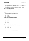
b11..............STA: Signaled Target Abort
This bit indicates that DS-1S terminates a transaction with Target Abort during a target cycle.
b12..............RTA: Received Target Abort
This bit indicates that a transaction is terminated with Target Abort while DS-1S is in the master memory
cycle.
b13..............RMA: Received Master Abort
This bit indicates that a transaction is terminated with Master Abort while DS-1S is in the master memory
cycle.
b14..............SSE: Signaled System Error
This bit indicates that DS-1S asserts SERR#.
b15..............DPE: Detected Parity Error
This bit indicates that DS-1S detects Address Parity Error or Data Parity Error during a transaction.